
Projection system

A technology of projection system and sensing signal, applied in the field of projection system, can solve problems such as unreliable operation, and achieve the effect of easy implementation and installation

Inactive Publication Date: 2005-10-19
KONINKLIJKE PHILIPS ELECTRONICS NV
View PDF0 Cites 4 Cited by
  • Summary
  • Abstract
  • Description
  • Claims
  • Application Information

AI Technical Summary

Problems solved by technology

[0011] However, this efficient control (LOC - light output control) cannot operate reliably if the sensor signal overlaps with disturbance components caused by brightness fluctuations from one color modulator as explained above

Method used


Image

  • Projection system
  • Projection system
  • Projection system

Examples


Embodiment Construction

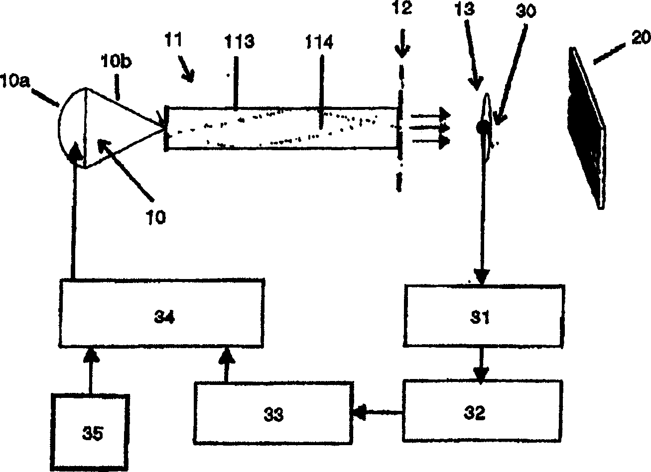
[0045] The brightness of the image reproduced on the projection system is controlled by a change in lamp current ( figure 1 , 4, 5, 7, 13 and 14). However, therein alternatively or additionally it is possible to change the intensity of the image by means of an electrically controllable optical filter additionally inserted in the radiation path between the lamp and the display and / or a grayscale mask in the form of a factor Brightness, which affects the brightness of image reproduction on a display through a grayscale mask. These two alternatives are specified in DE10220510.8 and they are especially suitable for very fast displays used in DLP systems. This published document is included in the present disclosure by reference, so that no separate description is required below.

[0046] The invention will first be described with reference to a projection system (scrolling color system) having an SCR-DMD operated by the second method described above. The structure and manner of...


PUM


Abstract

A projection system for image reproduction by means of at least one lamp (10) as well as a sensor (30;301,302,303) for generating a sensor signal for monitoring changes in the luminous flux generated by said at least one lamp (10) and for compensating these changes through a suitable control of the image reproduction is described. The projection system comprises a device (31; 32; 36; 37) for eliminating substantially periodic interference components from the sensor signal generated by the at least one sensor (30; 301, 302, 303). These interference components may be generated by an optical component such as in particular a color modulator (12) of the projection system. The invention thus renders possible an at least substantially interference-free compensation of fluctuations in the luminous flux generated by the lamp (10), for example owing to an unstable arc discharge, also in those color systems in which the positioning of the sensor (30) in the projection system is non-critical.

Description

technical field [0001] The invention relates to a projection system for image reproduction by means of at least one lamp and a sensor for generating a sensing signal monitoring changes in the luminous flux produced by said at least one lamp and for appropriate control by means of image reproduction compensate for these changes. Background technique [0002] The light source used in a projection system is usually formed by one or several high pressure gas discharge lamps (HID [High Intensity Discharge] lamps or UHP [Ultra High Performance] lamps). These lamps can in principle be operated with both direct current and alternating current. Both modes of operation have their advantages and disadvantages. AC operation prevents rapid corrosion of the electrodes and can increase the luminous efficacy of the lamp, but arc discharges are generally unstable due to polarity changes, allowing periodic brightness fluctuations or other image disturbances. However, neither of them can be...

Claims


Application Information

Patent Timeline
IPC IPC(8): H04N9/31H05B41/288H05B41/292
CPCH04N9/3114H05B41/2928H04N9/3155H04N9/3197H05B41/2882H04N9/3182H04N5/74G03B21/00H04N9/31
Inventor H·门希P·吕尔肯斯C·德佩W·D·库温伯格J·A·A·托宁R·H·A·M·聪德尔特
Owner KONINKLIJKE PHILIPS ELECTRONICS NV
Learn More