Polishing piece, polishing lap, and method of polishing glass panel for CRT

A grinding block and grinding disc technology, applied in abrasives, metal processing equipment, manufacturing tools, etc., can solve problems such as work efficiency, poor personnel efficiency, air pollution, and increased cost, and achieve high installation work efficiency and strong adhesion. , to ensure the effect of adhesion

Inactive Publication Date: 2005-10-19
POBAALE INDS +1
View PDF0 Cites 6 Cited by
  • Summary
  • Abstract
  • Description
  • Claims
  • Application Information

AI Technical Summary

Problems solved by technology

In addition, these metal molds must be prepared separately according to the size of the surface of the glass panel for cathode ray tubes, which requires a large investment in equipment, and requires multiple places for installing and storing the metal molds.
[0006] Second, the grinding block 206 provided with the concavo-convex portion for bonding on the lower end side must be provided with the groove portion 205 for bonding to the unvulcanized rubber material layer 203 by visual inspection when it is assembled to the vulcanization molding machine. The ends are confirmed one by one, and the work of pressing the grinding block 206 is performed, so the work efficiency and personnel efficiency are low.
In particular, these disadvantages tend to increase in the production process of large-area grinding discs used for grinding the glass panels of cathode ray tubes for ultra-wide large-screen TVs with a width of 40 cm or more that have increased in supply recently.
[0007] The 3rd, the power consumption that uses as the heat source that is used for the vulcanization of unvulcanized rubber material layer 203 is also very big, and the cooling after vulcanization of this rubber material layer 203 also needs very long time, also has from vulcanization The sulfur molding machine takes out a lot of manpower and labor, and the work efficiency and personnel efficiency are poor.
[0008] Fourth, in the manufacture of the grinding block 206 forming the groove portion 205 for bonding, it is necessary to use a cutting tool or the like to carry out the processing and forming steps of the groove portion 205 for bonding after the columnar block is formed, so the number of steps and the corresponding cost increase
[0009] Fifth, as the composition of the base layer 202 of the grinding block 210, it is a single layer of a vulcanized rubber material layer 203, or a structure in which a base 204 made of hard canvas is laminated in the middle layer. Steel or cast iron grinding blocks 201, 206 are added, so the base layer 202 cannot be recycled together with the grinding blocks 201, 206
If only the grinding blocks 201 and 206 must be recovered, the base layer 202 needs to be incinerated or melted, resulting in a corresponding increase in cost, air pollution, and water pollution. Therefore, the actual situation is that it is almost impossible to recycle at a low price and reuse

Method used


Image

  • Polishing piece, polishing lap, and method of polishing glass panel for CRT
  • Polishing piece, polishing lap, and method of polishing glass panel for CRT
  • Polishing piece, polishing lap, and method of polishing glass panel for CRT

Examples


Embodiment Construction

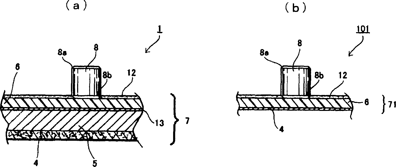
[0051] exist figure 1 In , the circular grinding disc 1 , alignment template 2 , and pressing auxiliary plate 3 in the present invention are shown as rough grinding discs on the surface of an aspherical glass panel for a cathode ray tube.

[0052] The grinding disc 1 consists of a lowermost rigid non-woven base layer 4 made of nylon fibers, a soft elastic base layer 5 made of sponge as an intermediate layer, and a base layer 7 formed of a block mounting layer 6 made of rigid polyurethane as the upper layer. and a plurality of cylindrical grinding blocks 8 fixed on substantially the entire surface of the upper surface of the block mounting layer 6 at predetermined intervals by an adhesive layer.

[0053] Moreover, the grinding disc 1 is passed through screws (not shown) that can be inserted into a plurality of threaded holes 9 and a threaded hole 10 formed in the center portion of the hard non-woven fabric base layer 4. , connected with the disc rotation drive mechanism (not ...


PUM


Abstract

A method for manufacturing polishing lap capable of firmly fixing a polishing piece onto the upper surface of a base layer without using a vulcanized forming device and a vulcanized forming process for unvulcanized rubber material layer, comprising the steps of forming both end parts of the piece in a general flat or a general recessed curve surface without providing any irregular part for increasing an engagement force on the outer periphery of the polishing piece, and pressingly fixing the piece into an adhesive layer on the base layer at any end side of piece, whereby a working efficiency and an economic efficiency can be remarkably increased more than that of a system pressingly fixed into the unvulcanized rubber material layer and, since the polishing piece is firmly fixed to the base layer, and accidents such as falling down and falling during polishing operation can be prevented.

Description

technical field [0001] The present invention relates to a grinding block, a grinding disc provided with the grinding block, and a method for grinding a glass panel for a cathode ray tube using the grinding disc. In the case of a cathode ray tube such as a machine, a grinding block used in a process of polishing the surface of a cathode ray tube panel, a grinding disc provided with the grinding block, and a method of polishing a glass panel for a cathode ray tube using the grinding disc. Background technique [0002] Conventionally, the technique described in Japanese Patent Publication No. 40-28753 has generally been used as such a grinding block and the structure of the grinding block, and the basic structure has basically not changed at present. That is, the glass panel for a cathode ray tube is mounted and fixed on a turntable with its outer surface facing upward, and is rotated approximately horizontally, and a grinding block is brought into rotational contact with the p...

Claims


Application Information

Patent Timeline
Patent Type & Authority Applications(China)
IPC IPC(8): B24D3/00B24D7/00B24D7/06
Inventor 神田隆生小滨尚希关口均本冈义人
Owner POBAALE INDS
Why Eureka
Try Eureka