Device for varying valve timing in an internal combustion engine

一种控制时间、内燃机的技术,应用在阀装置、传动装置、机械设备等方向,能够解决加速噪音产生、加大等问题,达到紧凑结构形式的效果

Inactive Publication Date: 2005-09-21
INA SCHAEFFLER KG
View PDF1 Cites 15 Cited by
  • Summary
  • Abstract
  • Description
  • Claims
  • Application Information

AI Technical Summary

Problems solved by technology

At the same time, however, the existing component play is also converted, so that the small meshing rotation backlash between the adjusting shaft and the mating counter gear meshing increases and accelerates the noise generation

Method used


Image

  • Device for varying valve timing in an internal combustion engine
  • Device for varying valve timing in an internal combustion engine
  • Device for varying valve timing in an internal combustion engine

Examples


Embodiment Construction

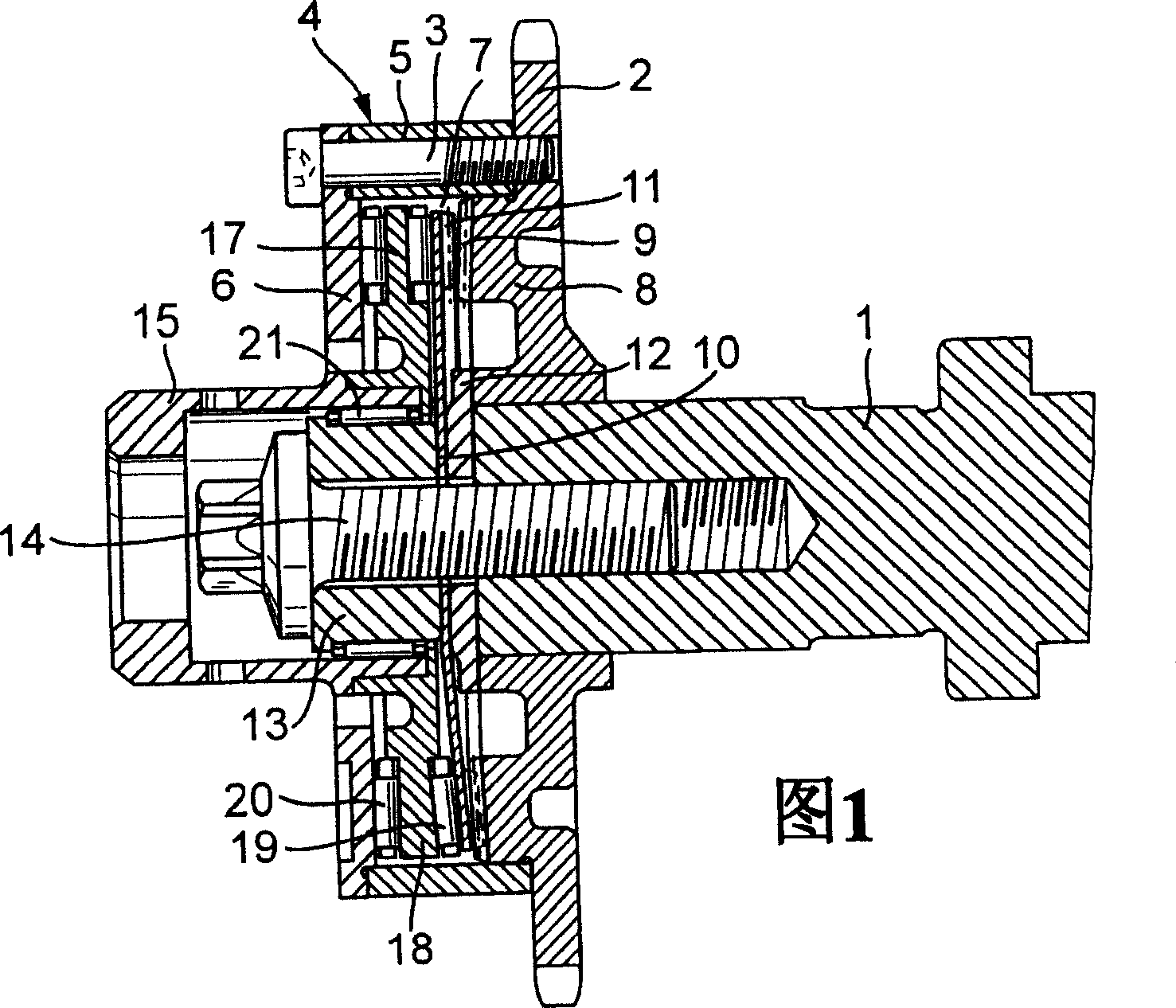
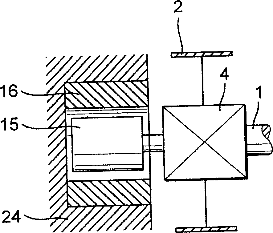
[0019] In FIG. 1 , the end section of the camshaft of the internal combustion engine is denoted by 1 , on which a drive wheel 2 , which is designed as a sprocket, is rotatably mounted. The drive wheel 2 is driven from a not shown driven wheel of a camshaft of the internal combustion engine via a chain, also not shown. It goes without saying that instead of a chain a toothed belt drive or a toothed drive can also be provided, wherein then there are corresponding drive wheels which match the pitch of the toothed belt. The housing 4 is clamped by means of the driving wheel 2 via the fastening screws 3 and consists of an annular housing part 5 and a disk-shaped housing wall 6 . The driving wheel 2 , the annular housing part 5 and the disk-shaped housing wall 6 together form the inner chamber 7 of the housing 4 .

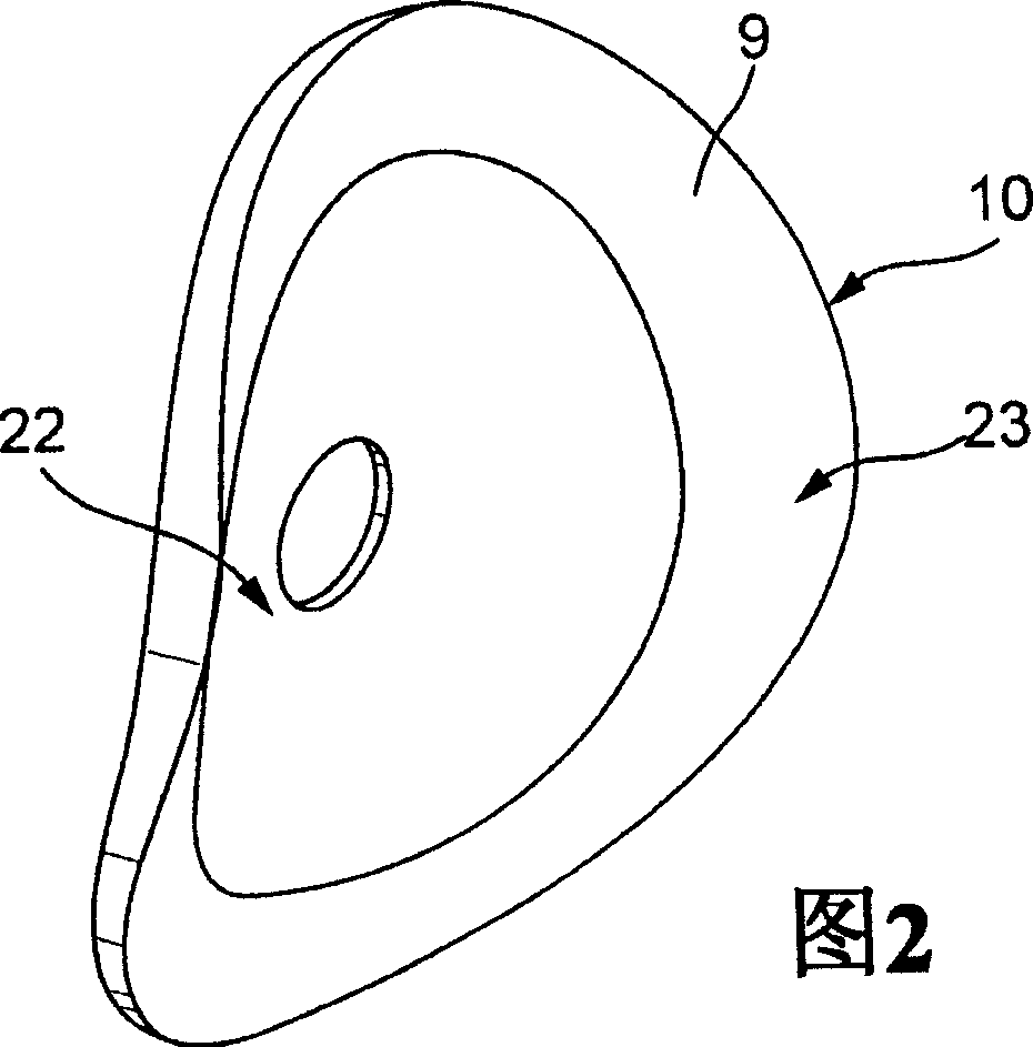
[0020] Drive wheel 2 has, on its end face close to interior space 7 , a section serving as adjustment element 8 , which has a first end face engagement 9 . A disc 10 d...


PUM


Abstract

A device for varying valve timing in an internal combustion engine comprises an adjusting mechanism for varying an angle of rotation between a drive pinion ( 2 ) and a camshaft (end portion of the camshaft , said adjusting mechanism being configured as a wobble transmission. The drive pinion ( 2 ) comprises a first front-end gearing ( 9 ) and a disk ( 10 ) comprises a second front-end gearing ( 11 ), which first and second front-end gearings mesh partially with each other, and the number of teeth of said front-end gearings differ from each other by at least one tooth. To reduce the overall dimensions of the device and avoid gearing lash, it is proposed, on the one hand, to connect the disk ( 10 ) rotationally fast to the camshaft ( 1 ) and on the other hand, to configure the disk ( 10 ) in axial direction of the camshaft ( 1 ) as a flexible element that can be deformed in axial direction by an adjusting device (thrust plate 17 ).

Description

technical field [0001] The invention relates to a device for varying the control time of an internal combustion engine, which has an adjusting device for varying the angle of rotation between the drive wheel and the camshaft and is designed as an axial eccentric transmission, with a first end face meshing with the drive Adjusting element with a wheel fixed torsion and with a disk in its radially outer region with a second end engagement, whose second end engagement is in an adjusting motion by means of a positioning device, wherein the end engagement is partly engaged, wherein the end engagement differ from each other by at least one tooth. Background technique [0002] Devices are known for varying the control time, in which the camshaft is hydraulically adjusted relative to the driving wheel, that is to say rotated by a piston moving in the axial direction of the camshaft and a helical tooth meshing operatively connected to the piston Adjustment, or hydraulic adjustment s...

Claims


Application Information

Patent Timeline
Patent Type & Authority Applications(China)
IPC IPC(8): F01L1/34F01L1/352F01L1/356F01L1/46
CPCF16H49/001Y10T74/19F01L1/022F01L2103/00F01L1/026F01L1/34F01L2101/00F01L1/356F01L1/46F01L1/352F01L1/024F01L2303/00F01L2301/00
Inventor 延斯·沙费尔马丁·施泰格瓦尔德乔纳森·黑伍德
Owner INA SCHAEFFLER KG
Why Eureka
Try Eureka