A fluid-dispensing circuit with check valves

A technology of one-way valve and circuit, which is applied in the direction of distribution device, liquid distribution, conveying or transfer device, special distribution device, etc. It can solve the problems of product flow pressure reduction, valve can not be sealed, system accuracy reduction, etc., to achieve convenient Effect of complete filling, improved conveying accuracy, and reduced risk of cavitation

Inactive Publication Date: 2005-09-21
赛皮尔斯色料设备股份有限公司
View PDF0 Cites 4 Cited by
  • Summary
  • Abstract
  • Description
  • Claims
  • Application Information

AI Technical Summary

Problems solved by technology

This deposit directly causes the valve to fail to seal, causing product to leak, and at the same time, the pressure of the product flow through the system is unexpectedly reduced
So system accuracy is reduced, especially when it relies on control systems that work based on stored theoretical data or calibration values ​​or even on feedback that presupposes correct valve action

Method used


Image

  • A fluid-dispensing circuit with check valves
  • A fluid-dispensing circuit with check valves
  • A fluid-dispensing circuit with check valves

Examples


Embodiment Construction

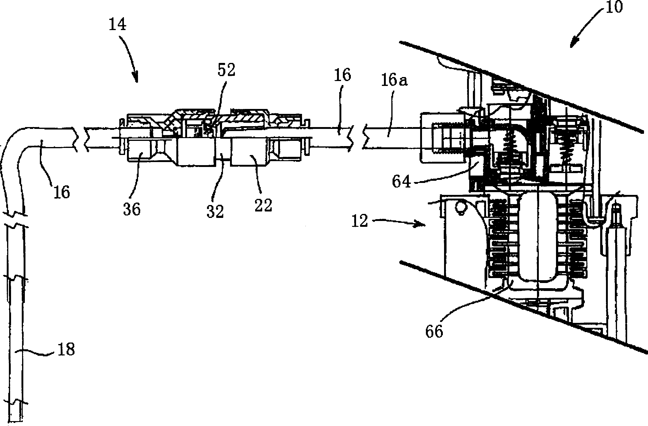
[0020] now refer to figure 1 , the distribution circuit 10 includes: a pump 12 with a variable volume chamber, such as a bellows pump or a diaphragm pump; a one-way delivery valve 14 mounted on the outside of the pump 12 and placed at the nozzle extending from the pump 12 18 in the delivery pipe 16.

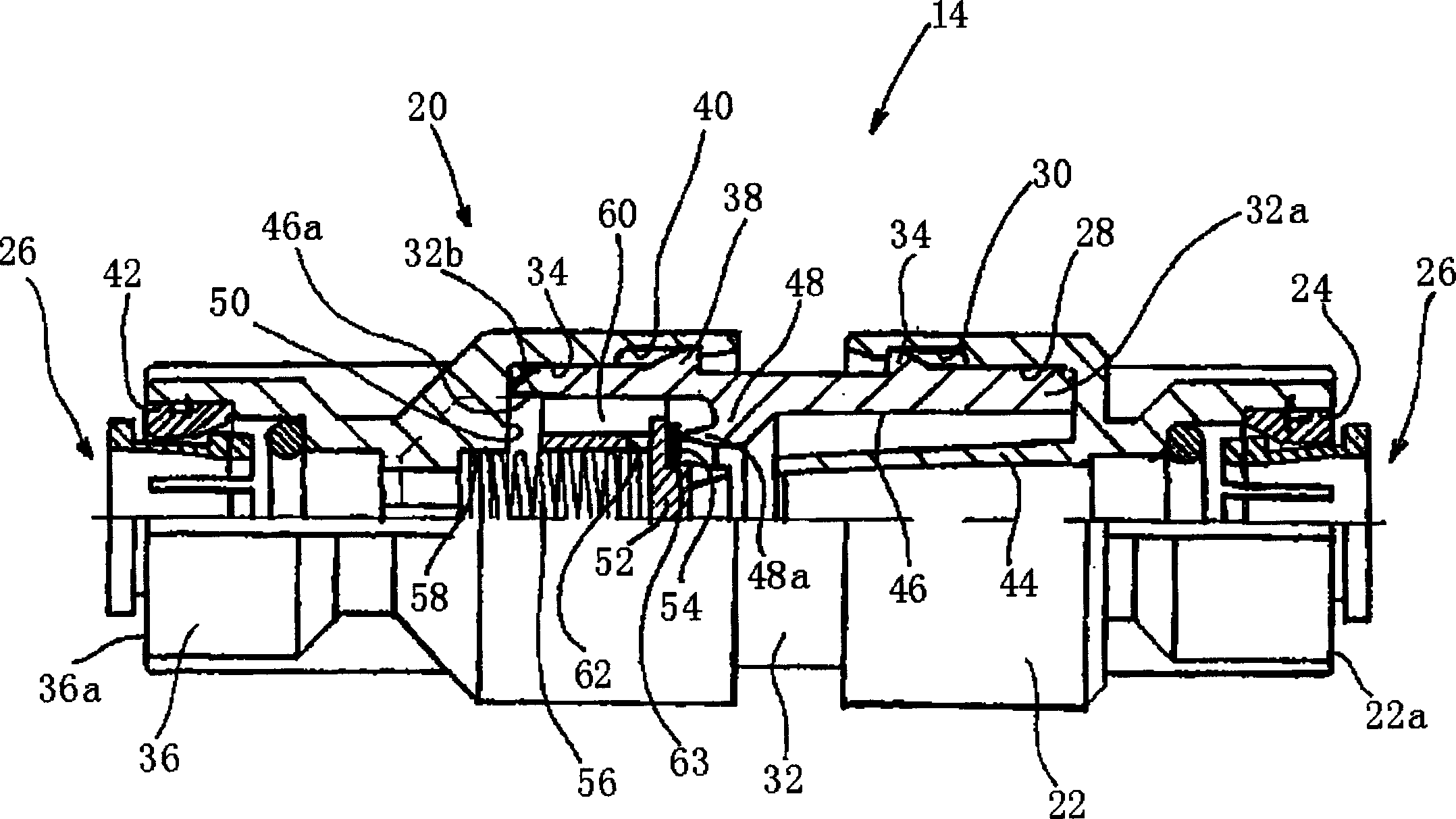
[0021] Transfer valve 14 establishes shell 20 (see figure 2 ), preferably but not limited to, including three hollow parts that can fit into each other. figure 2 In the illustrated embodiment, one end 22a of the inlet member 22 is provided with a sleeve 24 for insertion of a quick-fit tubing connection 26 of known type. The other end of the inlet part 22 has a hole 28 which is, preferably but not limited to, cylindrical and has an annular groove 30 on its side wall. One end 32 a of the guide member 32 is substantially cylindrical so that it can be inserted into the hole 28 , it is preferably but not limited to this shape, and a preferably annular tooth 34 is provided on its ...


PUM


Abstract

A circuit for dispensing fluids, in particular, dyes, inks paints and the like, comprises pump means (12) including a variable-volume chamber (66) with at least one flexible wall. The pump means (12) communicate with an output duct (16, 72) for dispensing the fluids. Two one-way valves (14, 94) are mounted in series in the output duct (16, 72).

Description

technical field [0001] This invention relates to circuits and machines for metering and dispensing fluids, especially dyes, inks, paints and similar products. [0002] The invention relates in particular to a dispensing circuit comprising a pump device comprising a variable volume chamber with at least one flexible wall, in which chamber the pump device is connected to an outlet tube for dispensing a fluid. [0003] The invention also includes machines in which one or more of the circuits described above are used. Background technique [0004] In the field of machines for metering and dispensing coloring fluids, diaphragm pumps are frequently used in conjunction with on-off valves that control the withdrawal of fluid from the reservoir and output from the nozzle. In fact, this particular combination behaves very precisely, especially when metering small quantities of product. However, existing machines experienced extended downtime due to cleaning of parts in the system. ...

Claims


Application Information

Patent Timeline
Patent Type & Authority Applications(China)
IPC IPC(8): F16K15/06B67D7/02B67D7/36B67D7/58F04B53/10F16K51/00F16L37/092
CPCF16L37/092B67D7/36B67D7/58B67D7/0255F16L37/0927
Inventor 安伯托·马拉齐乔治·曼弗雷迪尼莫妮卡·克洛莱奥波尔多·马扎维瑞
Owner 赛皮尔斯色料设备股份有限公司
Why Eureka
Try Eureka