Digital controlled self aligned micro mechanical optical switches in free space

A free space, digital control technology, applied in the direction of optics, optical fiber transmission, optical components, etc., can solve the problems of small size, difficulty in detection, difficulty in precise control of reflection angle, etc., to achieve simple structure, ensure accuracy and repeatability, Eliminate the effect of detecting the control circuit

Inactive Publication Date: 2005-08-31
SOUTHEAST UNIV
View PDF0 Cites 6 Cited by
  • Summary
  • Abstract
  • Description
  • Claims
  • Application Information

AI Technical Summary

Problems solved by technology

[0008] Technical problem: Aiming at the small size of MEMS devices, weak capacitance changes, and difficult detection, so that the precise control of the reflection angle of free space MEMS optical switches is difficult, the present invention solves the problem from the structural design, providing a digitally controlled self-positioning free space micro The mechanical optical switch realizes the fixed angle deflection and automatic positioning of the mirror surface, removes the complicated angle detection and control circuit, and realizes the direct digital control of the free space MEMS optical switch

Method used


Image

  • Digital controlled self aligned micro mechanical optical switches in free space
  • Digital controlled self aligned micro mechanical optical switches in free space
  • Digital controlled self aligned micro mechanical optical switches in free space

Examples


Embodiment Construction

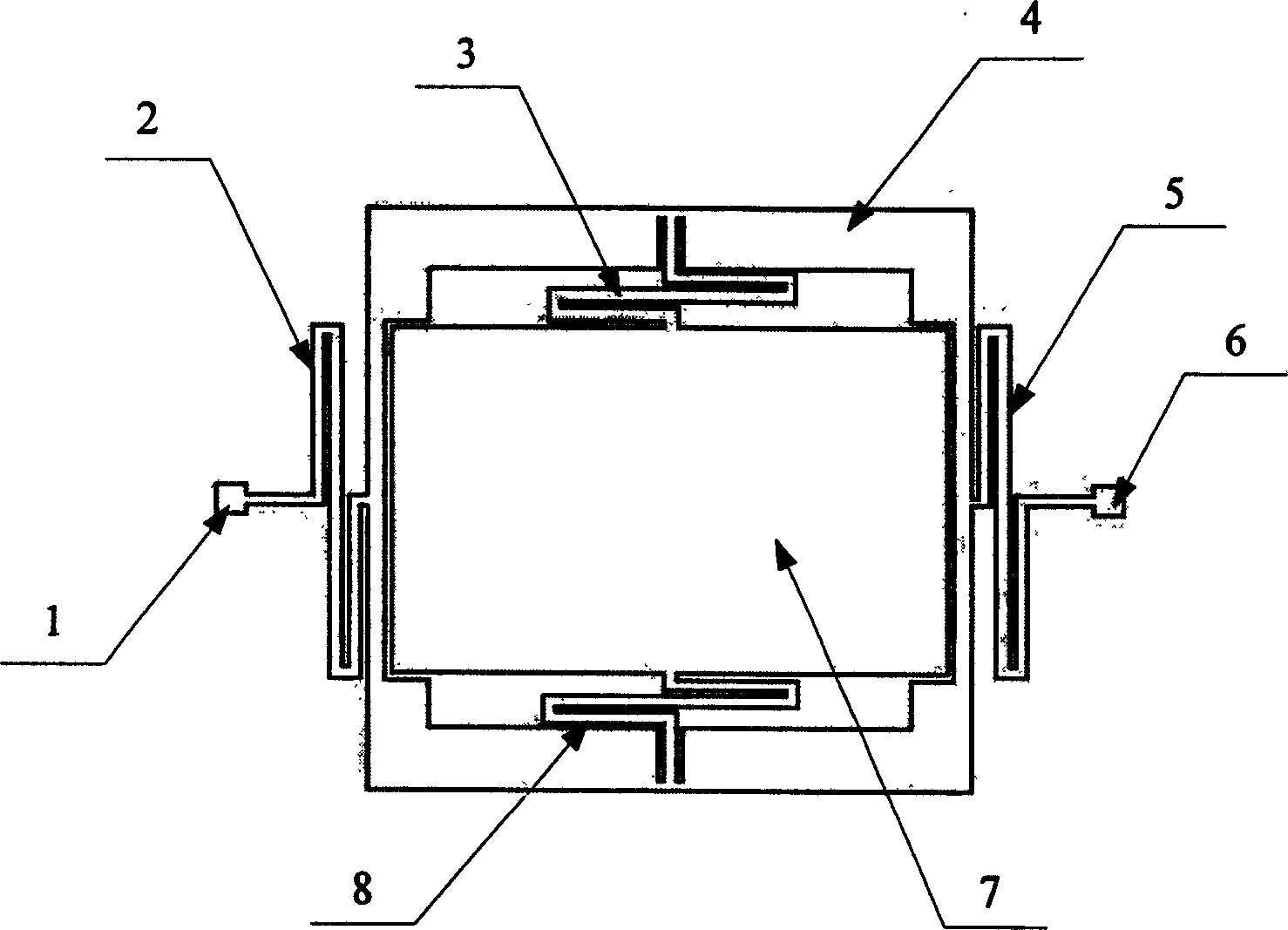
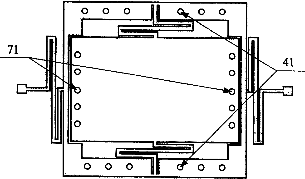
[0026] Structurally, the digitally controlled self-positioning free space micromechanical optical switch of the present invention consists of a left support point 1, a right support point 6, a left support beam 2, a right support beam 5, an upper support beam 3, a lower support beam 8, and a frame 4. Reflecting mirror surface 7 forms the main structure of the biaxial micromirror; wherein, reflecting mirror surface 7 is located in the middle of frame 4, and the two ends of left support beam 2 are respectively fixed with the outside of frame 4 and left support point 1, the right support beam 5 Both ends are respectively fixed to the outside of frame 4 and right support point 6; Fixed in the lower part of the frame 4, the upper end of the lower support beam 8 is fixed on the lower end of the mirror surface 7. An outer boss 41 and an inner boss 71 are provided on the backs of the frame 4 and the mirror surface 7 respectively. On the substrate under the main structure of the biaxi...


PUM


Abstract

The present invention relates to a numerically controlled self-positioning free space micromechanical optical switch. It is an optical switch device used for optical cross-connection in fiber-optic communication network. It has a biaxial micromirror main body structure formed from left supporting point, right supporting point, left supporting bean, right supporting beam, upper supporting beam, lower supporting beam, frame and reflecting mirror. Said invention also provides their connection mode.

Description

technical field [0001] The invention relates to an optical switch device, which is used for optical cross-connection in an optical fiber communication network, and belongs to the technical field of semiconductor micro-device manufacturing. Background technique [0002] With the continuous improvement of the informatization level of the whole society, the optical-electrical-optical switching mode in the current optical fiber communication network has become the "electronic bottleneck" to further expand the communication capacity. All-optical switching is the development direction of the optical fiber communication network, and optical cross-connection is The key to realizing all-optical switching, the optical switch is the core device in the optical cross-connect device. [0003] In recent years, with the improvement of application requirements and the development of science and technology, people have researched and developed a variety of optical swit...

Claims


Application Information

Patent Timeline
IPC IPC(8): G02B26/00H04B10/25
Inventor 李宏生黄继伟
Owner SOUTHEAST UNIV
Why Eureka
Try Eureka