
Frequency-current conversion circuit, equalizer, and optical disc apparatus

A frequency current conversion and circuit technology, applied in frequency to amplitude conversion, frequency measurement devices, emergency protection circuit devices, etc. Effect

Inactive Publication Date: 2005-08-17
ROHM CO LTD
View PDF1 Cites 6 Cited by
  • Summary
  • Abstract
  • Description
  • Claims
  • Application Information

AI Technical Summary

Problems solved by technology

However, when the speed of the optical disc device changes, it is difficult for the potential of node D to follow the change in the frequency of the input clock with proper timing.

Method used


Image

  • Frequency-current conversion circuit, equalizer, and optical disc apparatus
  • Frequency-current conversion circuit, equalizer, and optical disc apparatus
  • Frequency-current conversion circuit, equalizer, and optical disc apparatus

Examples


Embodiment Construction

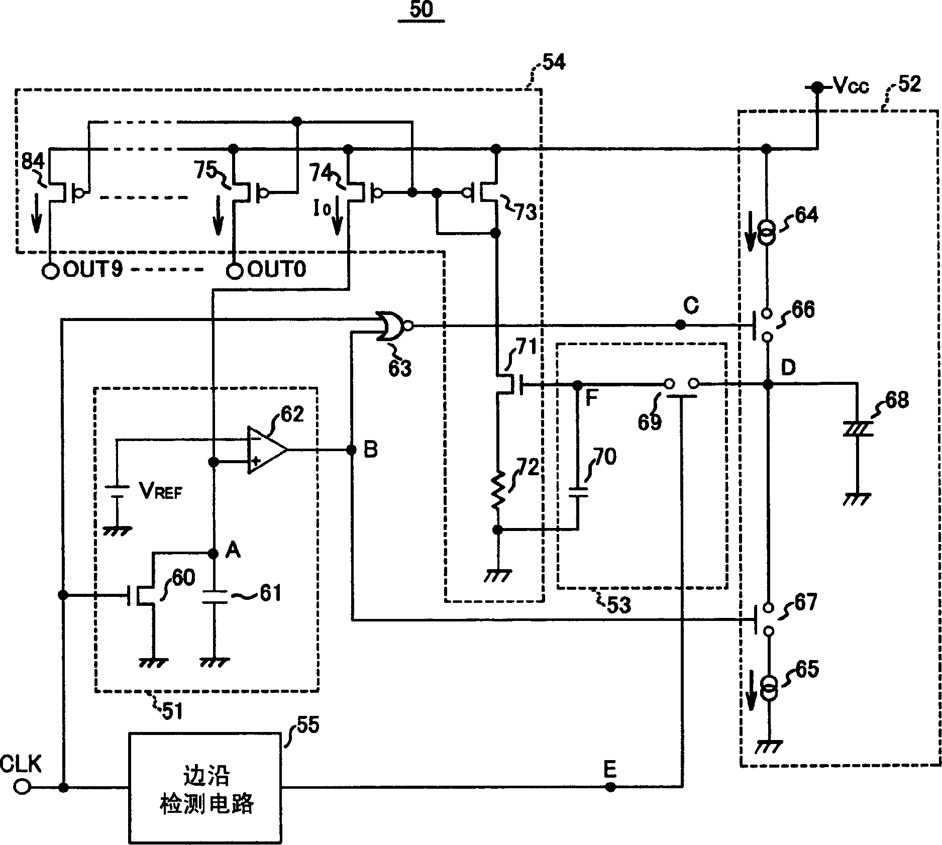
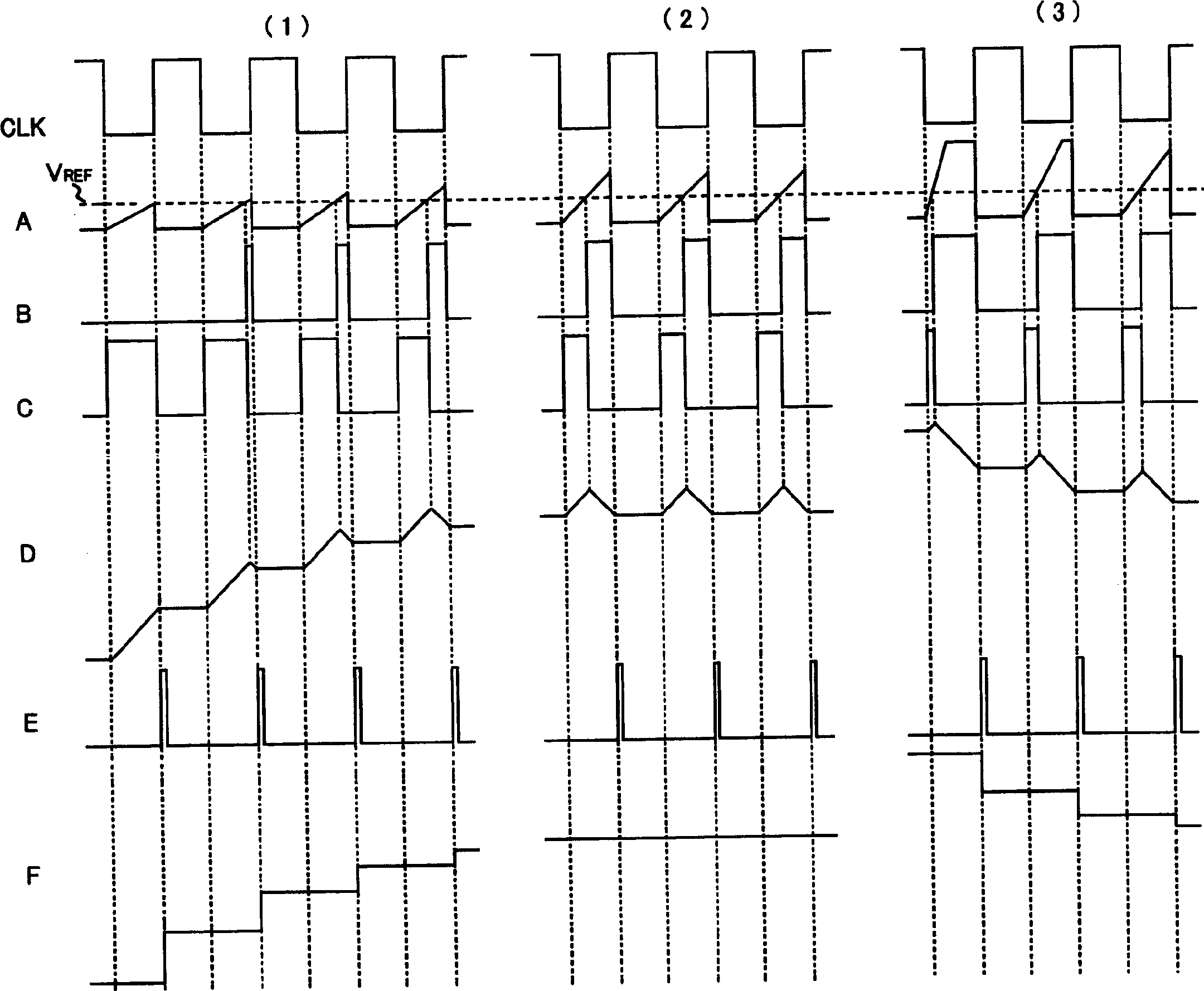
[0028] Next, the frequency-to-current conversion circuit of the preferred embodiment of the present invention will be described. figure 1 is a circuit diagram of the frequency-to-current conversion circuit 50 . figure 2 is a waveform diagram showing waveforms of voltages at the respective nodes of the frequency current conversion circuit 50, that is, the input clock of the input clock terminal CLK and the nodes A to F (to be described next), in which parts (1), (2), (3) show the output reference current I of the transistor 74 (described later) 0 Cases with three different sizes. The frequency-current conversion circuit 150 generates an output current corresponding to the frequency of the input clock. The frequency-current conversion circuit 150 includes a comparison circuit 51 , a charge / discharge circuit 52 , a sample-and-hold circuit 53 , a voltage-current conversion circuit 54 , and an edge detection circuit 55 . The comparison circuit 51 includes a first capacitor 61 ...


PUM


Abstract

A frequency-current conversion circuit permits stabilization of the frequency characteristic of an equalizer that is used in a high-speed optical disc apparatus. The frequency-current conversion circuit includes a comparison circuit that includes a first capacitor that is charged by an output reference current and is forcibly discharged over a predetermined period from the change point of the input clock of the input clock terminal, and that compares the voltage produced in the first capacitor with a reference voltage, a charging / discharging circuit that includes a second capacitor that is charged and discharged in accordance with the output of the comparison circuit and that outputs a voltage that is produced in the second capacitor, a sample and hold circuit that samples and holds the output voltage of the charging / discharging circuit within the predetermined period, and a voltage-current conversion circuit that converts the held voltage to the output reference current and an output current that is proportional to the output reference current.

Description

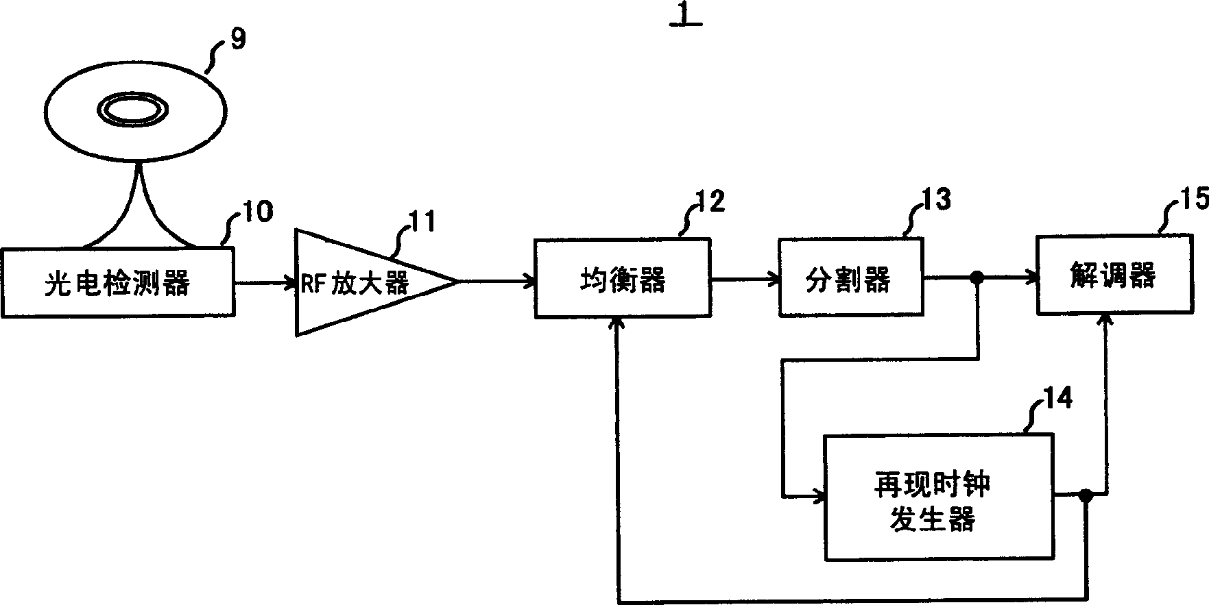
technical field [0001] The present invention relates to a frequency current conversion circuit which generates an output current corresponding to the frequency of an input clock, an equalizer comprising the frequency current conversion circuit and having a steep frequency characteristic, and an equalizer comprising the equalizer CD device. Background technique [0002] Optical disk devices have such image 3 The basic structure of the signal processing block is shown. That is to say, the optical disc device 1 detects optical signals according to code points in an optical disc 9 such as a compact disc (CD) or a digital versatile disc (DVD) by means of a photoelectric sensor 10, amplifies the detected signal by an RF amplifier 11, and This signal (differential RF signal) is corrected by the equalizer 12 . Then, the optical disc device 1 binarizes the corrected signal through a slicer 13 , and then demodulates (reproduces) digital data from the binary signal through a demodul...

Claims


Application Information

Patent Timeline
Patent Type & Authority Applications(China)
IPC IPC(8): G01R23/06G11B7/00G11B20/10H02H7/00
CPCG11B20/10046G11B20/10009G11B20/10222B65B1/24B65B65/02
Inventor 滨口刚
Owner ROHM CO LTD
Learn More