
Reactor combustion control method and reactor

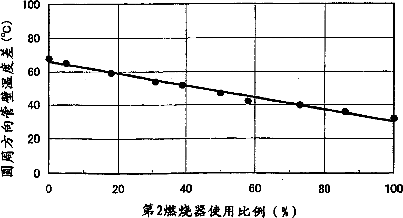
A control method and technology of a reaction furnace, applied in the direction of combustion method, combustion type, combustion equipment, etc., can solve the problems of reaction tube heat (reduced heat transfer efficiency, lack of uniformity in heating, etc.), to reduce temperature difference and yield little effect

Inactive Publication Date: 2005-07-20
CHIYODA CORP
View PDF8 Cites 4 Cited by
  • Summary
  • Abstract
  • Description
  • Claims
  • Application Information

AI Technical Summary

Problems solved by technology

For this reason, the heating of each reaction tube lacks uniformity, and there arises a problem that the amount of heat received (heat transfer efficiency) of the reaction tube as a whole decreases.

Method used


Image

  • Reactor combustion control method and reactor
  • Reactor combustion control method and reactor
  • Reactor combustion control method and reactor

Examples


Embodiment Construction

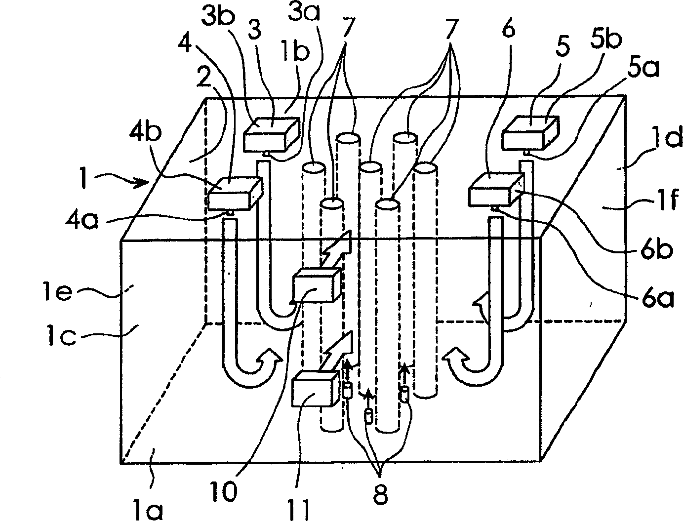
[0039] Hereinafter, embodiments of the present invention will be described in detail with reference to the drawings. figure 1 It is a figure which shows the schematic structure of an example of embodiment of the reforming reaction furnace which used this invention for a test. figure 1 Among them, the mark 1 indicates the furnace body with the combustion chamber 2 inside. The furnace body 1 is provided with a bottom wall (hearth) 1a and an upper wall (roof) 1b constituting a pair of wall portions, constituting a width direction (from figure 1 The sidewalls 1c and 1d of a pair of wall parts, which are seen as being perpendicular to the front-rear direction of the paper surface, constitute the lateral direction (from figure 1 See side walls 1e and 1f of a pair of wall portions in the left-right direction).

[0040] The bottom wall (hearth) 1a of the furnace body 1 is supported by a support structure not shown in the figure. On the upper wall (furnace roof) 1b of the furnace ma...


PUM


Abstract

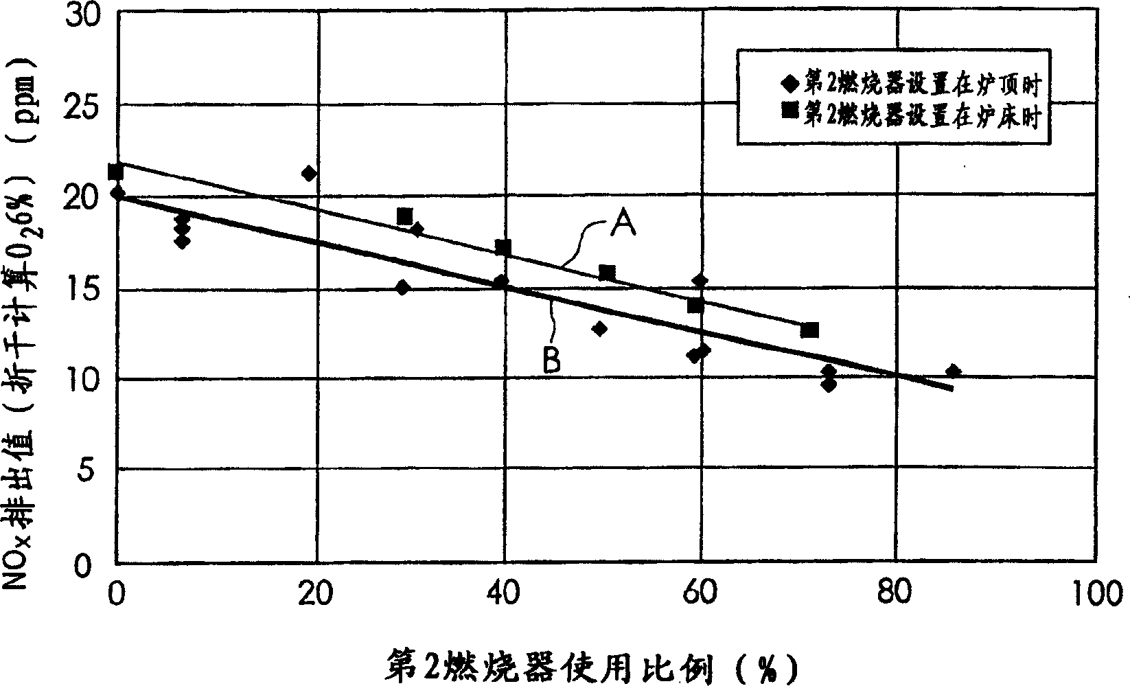
A reactor combustion control method using a high temperature air combustion technology capable of reducing a temperature difference in a reactor without producing cracking and caulking in reaction tubes and the reactor controlled by using the method, the reactor wherein second burners ( 8 ) are disposed in a space formed between two or more reaction tubes ( 7 ) adjacent to each other so as to inject fuel in the extending direction of the reaction tubes ( 7 ), and partial combustion air feeding devices ( 10 ) and ( 11 ) for the second burners discharging exhaust gas in a combustion chamber ( 2 ) to the outside of the reactor through a permeable heat reservoir and feeding combustion air heated to a high temperature by the latent heat of the heat reservoir to the second burners ( 8 ) are installed; the method comprising the steps of raising the temperature in the reactor by the combustion of only the first burners ( 3 a) to ( 6 a) until the inside of a reactor body ( 1 ) is brought into a high temperature air combustion state, starting the combustion of the second burners ( 8 ) after the inside of the reactor body ( 1 ) is brought into the high temperature air combustion state, and decreasing the amount of combustion of the plurality of first burners ( 3 a) to ( 6 a) according an increase in combustion amount of the second burners ( 8 ) whereby a necessary combustion state can be provided.

Description

technical field [0001] The invention relates to a reaction furnace using high-temperature air combustion technology. Background technique [0002] Japanese Patent Application Laid-Open No. 11-179191 (Japanese Patent Application No. 9-357263) discloses a technique for improving the reaction efficiency of several reaction tubes. This technology uses a high-temperature air combustion type regenerative combustion device to increase the temperature in the furnace. In the furnace, several reaction tube groups composed of several reaction tubes are arranged side by side side by side. [0003] In addition, JP-A-2001-152166 (Japanese Patent Application No. Hei 11-343624) discloses a technology related to a reaction furnace using a high-temperature air combustion technology. The high-temperature air combustion technology mentioned here refers to the technology of preheating the combustion air to a high temperature above 800°C, blowing the combustion air into the combustion chamber at...

Claims


Application Information

Patent Timeline
Patent Type & Authority Applications(China)
IPC IPC(8): F23C1/00F23C5/08F23L15/02
CPCF23C5/08F23L15/02Y02E20/34
Inventor 毛利孝明吉冈利晃穗积良和汐崎彻长谷川敏明持田晋
Owner CHIYODA CORP
Learn More