
Continuously variable transmission metal belt, process for producing metal ring, and process for measuring shape of metal ring

By forming a protrusion on the side edge of the metal ring and grinding it, combined with the lubrication effect of the laminated structure, the problem of short fatigue life of the metal ring side edge of the continuously variable transmission is solved, and higher durability and centering functions are achieved.

Inactive Publication Date: 2005-07-13
HONDA MOTOR CO LTD
View PDF1 Cites 2 Cited by
  • Summary
  • Abstract
  • Description
  • Claims
  • Application Information

AI Technical Summary

Problems solved by technology

[0004] However, in the above-mentioned conventional technology, although the fatigue life of the side edge of the metal ring is considered based on the bending stress, the V-shaped surface and the Due to the Hertzian point contact stress caused by the contact of the neck of the metal member, it is difficult to effectively extend the fatigue life of the side edge of the metal ring

Method used


Image

  • Continuously variable transmission metal belt, process for producing metal ring, and process for measuring shape of metal ring
  • Continuously variable transmission metal belt, process for producing metal ring, and process for measuring shape of metal ring
  • Continuously variable transmission metal belt, process for producing metal ring, and process for measuring shape of metal ring

Examples


Embodiment Construction

[0022] Hereinafter, an embodiment of the present invention will be described based on the drawings attached to the embodiments of the present invention.

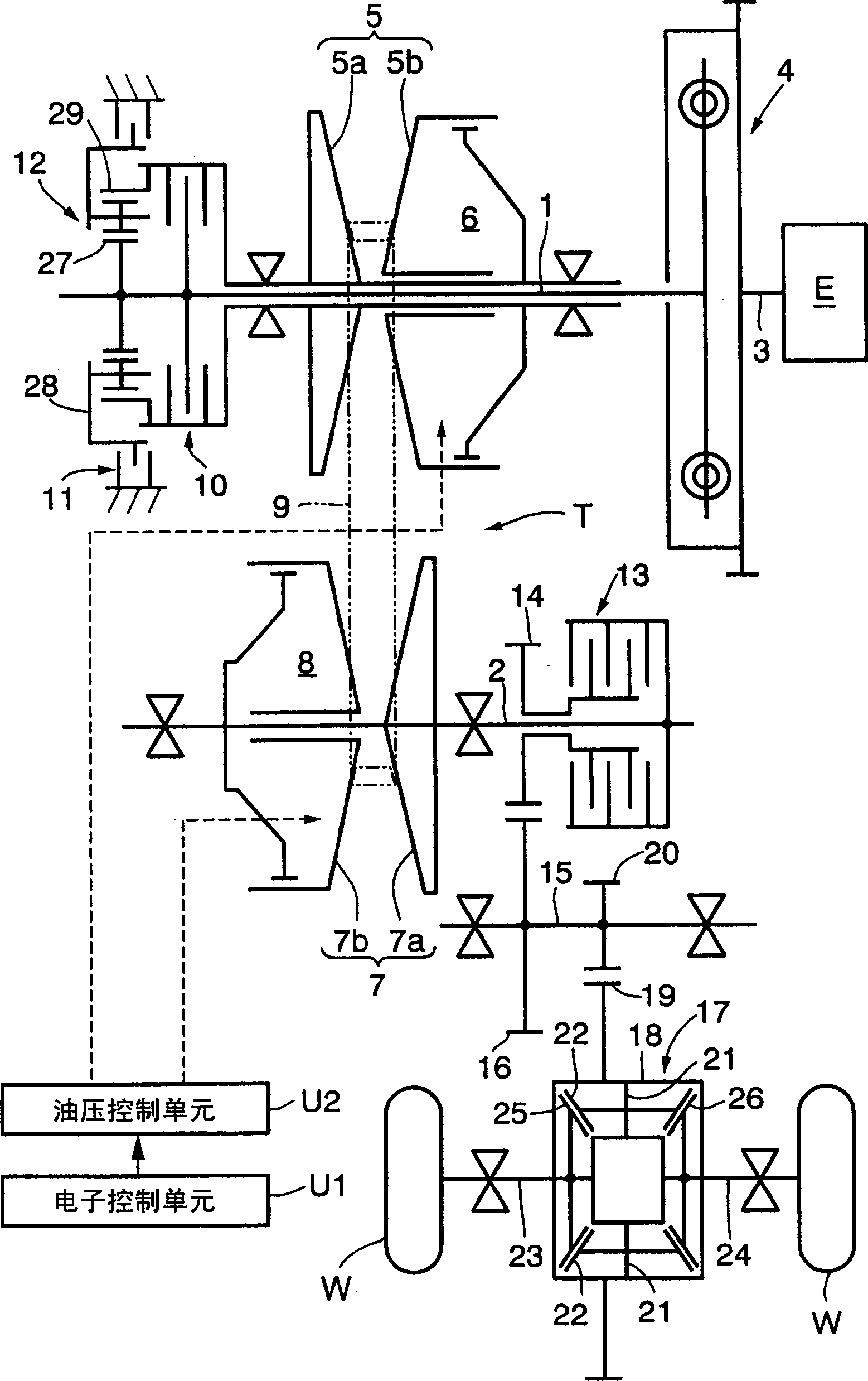
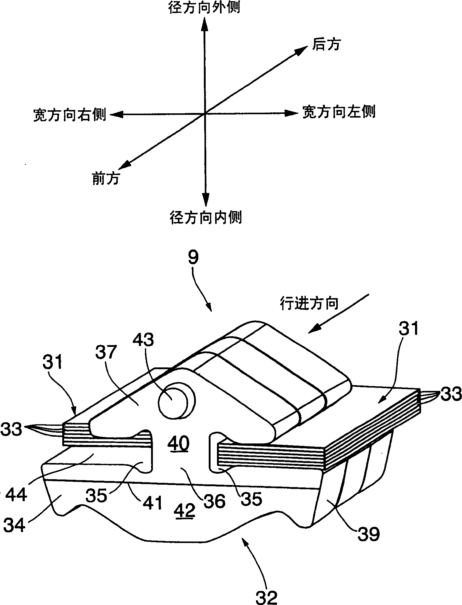
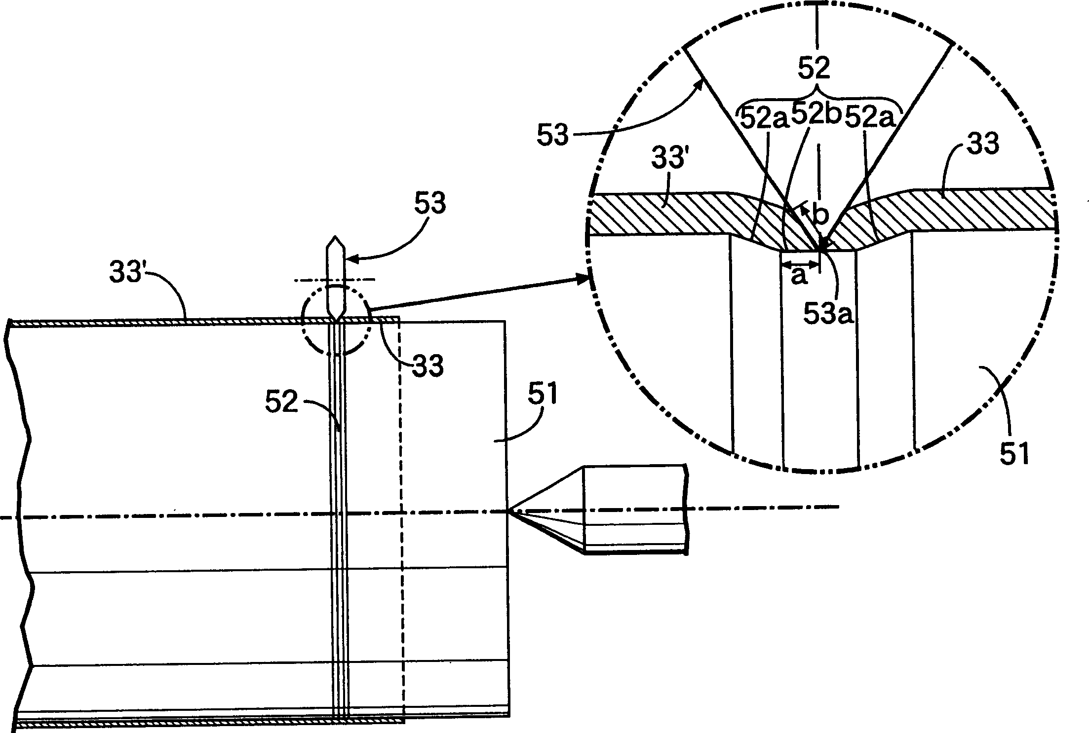
[0023] Figure 1 to Figure 8 is a diagram showing an embodiment of the present invention, figure 1 It is a schematic diagram of the power transmission system of a vehicle equipped with a metal belt continuously variable transmission, figure 2 is a partial perspective view of the metal ring, image 3 It is an explanatory diagram of the spinning process of the metal ring, Figure 4 It is a figure showing a cut metal ring and a ground metal ring, Figure 5 It is a figure which shows the state in which the metal ring of an Example and a comparative example contact the V-shaped surface of a pulley, Figure 6 is a graph showing the stress acting on the metal ring in Examples and Comparative Examples, Figure 7 is an enlarged view of the end of the metal ring assembly, Figure 8 It is explanatory drawing of the method of mea...


PUM


Abstract

A method for manufacturing a metal belt and a metal ring for a continuously variable transmission, and a method for measuring the shape of the metal ring, wherein the most protruding part is projected toward the width direction of the side edge of the metal ring (33) of the metal belt for a continuously variable transmission (33c) is located between the radial center surface (C) and the radial inner peripheral surface (I) of the metal ring, the protruding part, the position where it contacts the V-shaped surface (38) of the pulley (5, 7) (P) is closer to the central plane (C) in the radial direction than the inner peripheral surface (I) relative to the radial direction of the metal ring, so as to reduce the bending caused by the bending of the metal ring (33) wound on the pulley The sum of the compressive stress and the Hertzian point contact stress caused by the contact between the protrusion and the V-shaped surface of the pulley can improve the fatigue life of the metal ring compared with the comparative example. In addition, when the metal rings are laminated, recesses for retaining oil are formed between these side edges, and the sliding surfaces of the adjacent metal rings can be effectively lubricated, and the durability can be further improved.

Description

technical field [0001] The present invention relates to a metal belt for a continuously variable transmission that supports a plurality of metal members on a metal ring assembly in which annular metal rings are laminated in multiple layers, a method for manufacturing the metal ring, and a method for measuring the shape of the metal ring . Background technique [0002] It is known from the following Patent Document 1 that in such a metal ring of a metal belt for a continuously variable transmission, plastic deformation is carried out by making the portion close to the side edge gradually become thinner outward in the width direction of the metal ring, so as to reduce the The fatigue life is prolonged by the compressive stress and tensile stress of the side edge generated by the bending of the metal strip. [0003] [Patent Document 1] Japanese Patent Publication No. 6-6970 [0004] However, in the above-mentioned conventional technology, although the fatigue life of the side...

Claims


Application Information

Patent Timeline
Patent Type & Authority Applications(China)
IPC IPC(8): F16G5/16
CPCF16G5/16
Inventor 青山英明矢崎彻村上学金原茂
Owner HONDA MOTOR CO LTD
Learn More