
Resilient brace

A braced, elastic technology used in the direction of springs, springs/shock absorbers, elongated structural members for load bearing, etc.

Inactive Publication Date: 2005-07-06
LAFARGE PALTRES SA
View PDF1 Cites 1 Cited by
  • Summary
  • Abstract
  • Description
  • Claims
  • Application Information

AI Technical Summary

Problems solved by technology

Although the advantage of this brace is that it is just a piece of metal, the disadvantage is that under the action of pressure or tension, the bent part of the brace is easy to "roll up" or "stretch", so the brace is made rigid, so it is easy to transmit vibration force

Method used


Image

  • Resilient brace
  • Resilient brace
  • Resilient brace

Examples


Embodiment Construction

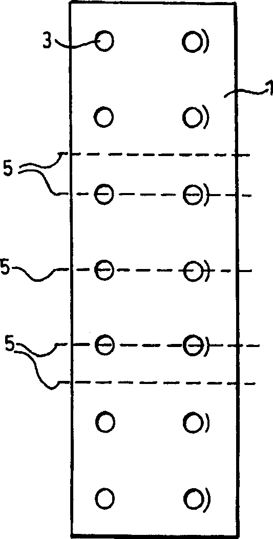
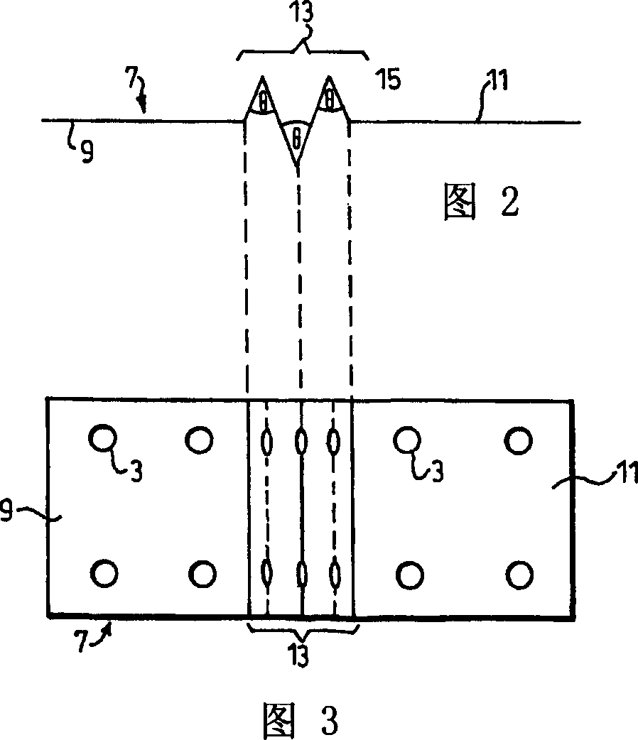
[0024] figure 1 A planar elongated die-cut sheet 1 of spring steel from which an elastic brace according to an embodiment of the invention can be produced is shown. Die-cut sheet material 1 is arranged with many holes 3 in two rows equidistant along its central long axis, and the holes 3 in each row are equidistant from each other and distributed in pairs along the transverse direction. The elastic brace according to the embodiment of the present invention can be made by bending the die-cut sheet material 1 along the fold line 5 in exchange directions. Fold line 5 passes in the middle of two pairs of holes 3 except that the outermost two are equidistant, and all the others pass through each pair of holes 3 . The arrangement of the folding lines directly affects the working mode of the elastic braces, which will be described in detail below with reference to FIG. 2 .

[0025] Figure 2 shows the figure 1 Elastic braces made of die-cut sheets. The first and second planar conn...


PUM


Abstract

A resilient brace ( 7 ) has first and second attachment portions ( 9, 11 ) formed at either end and a resilient portion ( 13 ) located therebetween, the resilient portion comprising a plurality of planar sections ( 15 ) orientated in a corrugated manner. The attachment portions lie on the same plane on which a stress axis is also located. The planar sections ( 15 ) are angled relative to one another and to the attachment portions so that each planar section ( 15 ) extends laterally of the stress axis.

Description

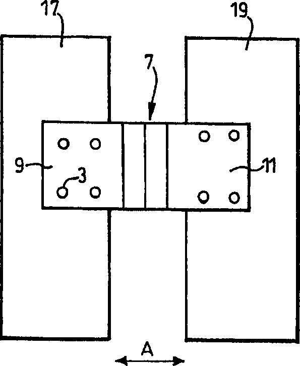
field of invention [0001] The invention relates to elastic braces for holding together two sections of a studded partition wall. Background technique [0002] Partition wall construction with studs is a common method of interior wall construction in the construction industry. Stud walls consist of a frame of vertical and horizontal beams to which, for example, gypsum boards are fixed to form the interior walls of a building. In order to improve the sound insulation effect of the partition wall, an existing method is to build a "double-frame partition wall", and two parts of the vertical rib partition wall are put together, and there is a gap between the two parts. The problem with double-frame partitions is that larger than a certain size, the inherent flexibility of stud partitions makes each side of the partition prone to bowing. To avoid this, the two parts of the partition wall are fixed with pallets. But rigid pallets transmit acoustic vibrations through the gap, thu...

Claims


Application Information

Patent Timeline
Patent Type & Authority Applications(China)
IPC IPC(8): E04B1/82E04B2/74E04B9/18E04C3/02F16F1/18F16F1/22
CPCE04B2/7412E04B2001/8254E04B2009/186E04C2003/026F16F1/185F16F1/22E04B2/72E04B2/74E04B9/18
Inventor C·沃克
Owner LAFARGE PALTRES SA
Learn More