Post-construction anchor, and drill bit for drilling prepared holes therefor

A threaded bottom hole and post-construction technology, used in stone processing equipment, stone processing tools, metal processing equipment, etc., can solve the problems of pulling out the fixture and the state of insufficient close contact again, and achieve excellent pulling endurance, Excellent workability and usability

Inactive Publication Date: 2005-07-06
ZEN KENCHIKU SEKKEI JIMUSHO TOKIOTOKYO
View PDF1 Cites 4 Cited by
  • Summary
  • Abstract
  • Description
  • Claims
  • Application Information

AI Technical Summary

Problems solved by technology

On the other hand, if the pull-out force is eliminated, the state where the expansion part and the taper surface on the side of the threaded bottom hole are in close contact again is not sufficient, and a gap may be generated between the two depending on the situation, so when the load is eliminated After that, when the pull-out force acts again, there is a possibility that the retainer may be pulled out due to its initial load, which is not desirable

Method used


Image

  • Post-construction anchor, and drill bit for drilling prepared holes therefor
  • Post-construction anchor, and drill bit for drilling prepared holes therefor
  • Post-construction anchor, and drill bit for drilling prepared holes therefor

Examples


Embodiment Construction

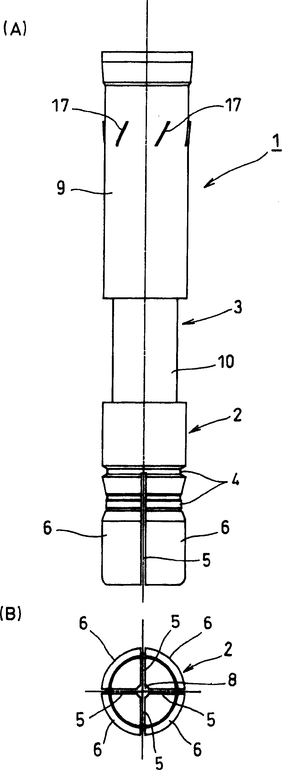
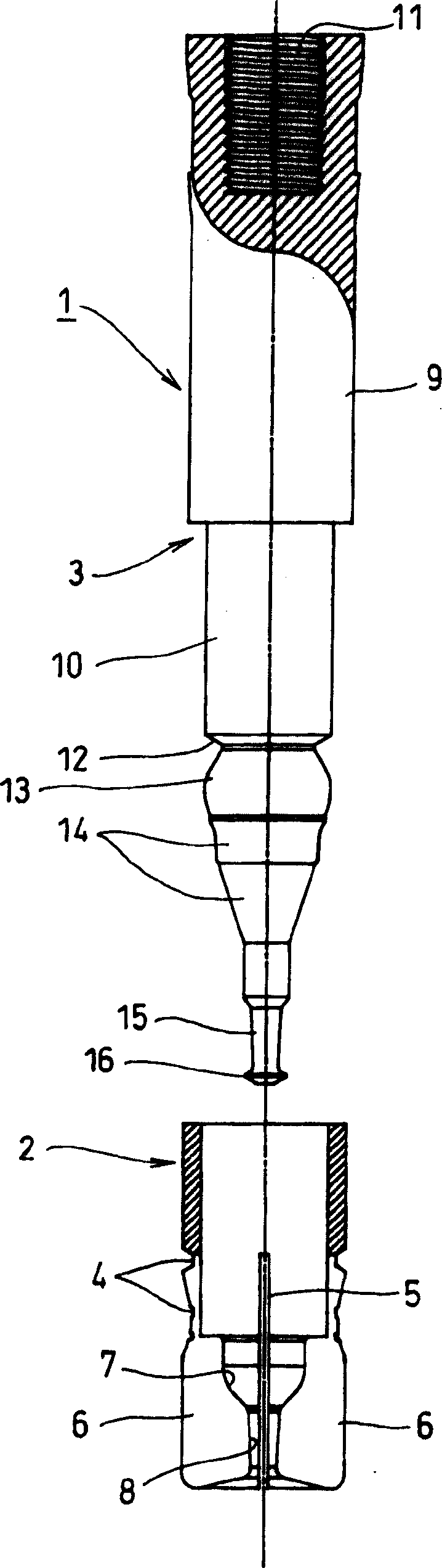
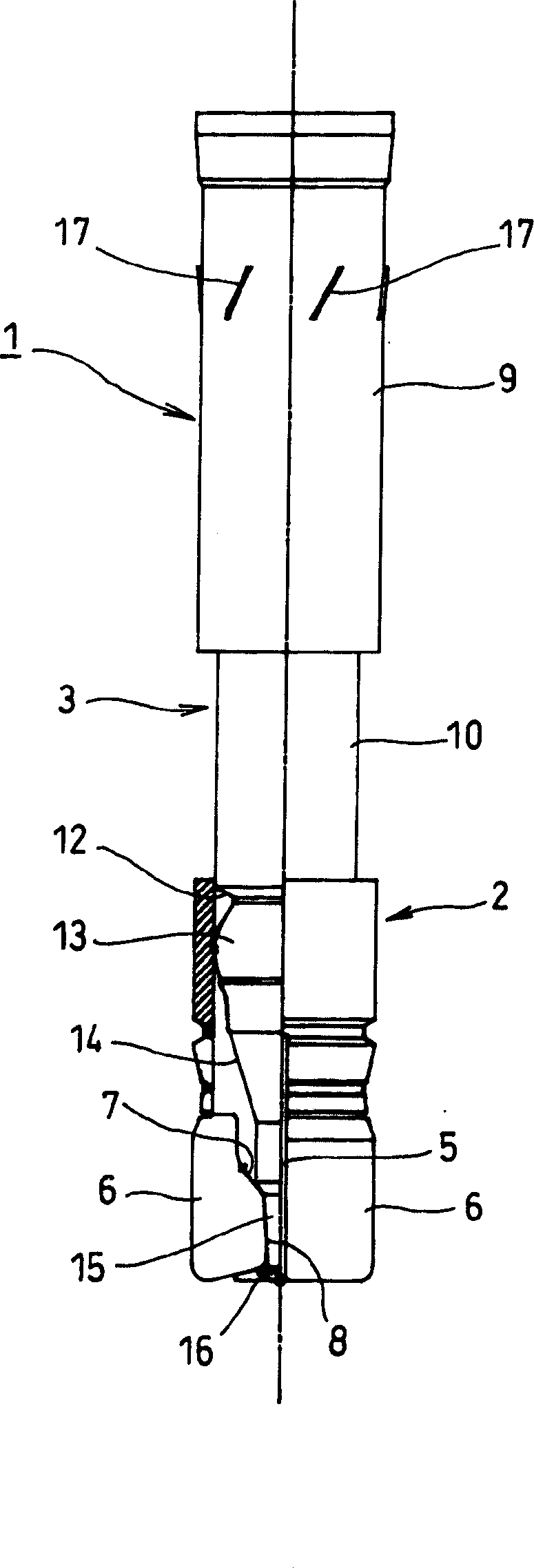
[0082] Figure 1-4 It is a diagram showing a preferred first embodiment of the post-construction anchor (hereinafter referred to as the anchor) related to the present invention, especially figure 1 (A) and (B) respectively represent the front view and bottom view of the fixture, figure 2 is to represent its disassembled anatomical view, and again, image 3 yes means figure 1 Half-section view of (A), Figure 4 It is a cross-sectional view showing the state before expansion and the state after expansion of the composite sleeve. In addition, this first embodiment corresponds to the invention described in claims 1-7.

[0083] Such as figure 1 , 2 As shown, the holder 1 is formed by a hollow cylindrical sleeve 2 and a substantially stepped shaft-shaped plug 3 pressed into the sleeve 2 as an expansion element.

[0084] On the outer peripheral surface of the sleeve 2, in addition to forming a plurality of peripheral grooves 4, the lower half of the sleeve 2 is cut into a col...


PUM


Abstract

Fixer (1) is suitable for threaded bottom hole (19) of undercut type, and this threaded bottom hole (19) expands in diameter near the hole bottom in a conical shape, has sleeve (2) and plug (3), and this sleeve ( 2) It has an expansion part (6); the plug (3) is inserted into the sleeve (2) to form a tapered part (14) for expanding the expansion part (6). If the plug (3) is pushed in with the sleeve (2) dropped to the bottom of the threaded bottom hole, one side will expand the expansion part (6) until it meets the taper surface (21a) of the threaded bottom hole (19) Tightly combined, one side is concave-convex fitting between the annular protrusion (13) and the fitting groove (7). At the same time, through the reaction force at the bottom of the hole produced by the drop of the plug (3) to the bottom of the threaded bottom hole (19), the expansion part (6) is pressed against the taper surface (21a) of the threaded bottom hole. Next, complete the construction. At the same time as this construction is completed, tensile resistance equivalent to that of steel can be obtained immediately without applying external tensile force.

Description

technical field [0001] The present invention relates to the improvement of post-construction anchors that are embedded on the basis of drilling and perforating existing concrete structures, and in particular to so-called anchors that can obtain a tensile strength equal to that of steel. Mechanical and undercut type post construction fixator. Background technique [0002] As such post-construction anchors, there have been various structures in the past. In particular, in recent years, due to the need for enhanced earthquake resistance, so-called undercuts that can obtain a tensile strength equal to the tensile strength of steel have been proposed so far. type post-construction anchors (for example, refer to International Publication No. 01 / 06070 brochure). [0003] In more detail, the general post-construction anchor is composed of a sleeve with an expansion part and a plug (expansion element) inserted therein for expanding the above-mentioned expansion part. On the other h...

Claims


Application Information

Patent Timeline
Patent Type & Authority Applications(China)
IPC IPC(8): B23B51/00B28D1/14F16B13/08F16B13/12
CPCB23B51/0045B28D1/146F16B13/0833F16B13/0858F16B13/126E04G23/0229E04G23/024E04G23/0237
Inventor 佐藤善则
Owner ZEN KENCHIKU SEKKEI JIMUSHO TOKIOTOKYO
Why Eureka
Try Eureka