Pcd with transmitted RF power strength indicator and warning system
A technology of indicating device and communication device, applied in power management, transmission system, communication between multiple stations, etc., can solve the problems of not providing user transmit signal strength indication, limited radio frequency power, etc.
- Summary
- Abstract
- Description
- Claims
- Application Information
AI Technical Summary
Problems solved by technology
Method used
Image
Examples
no. 1 example
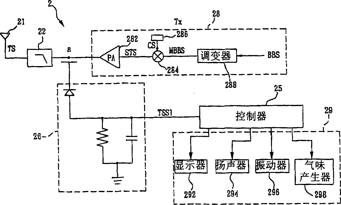
[0042] figure 2 It is a block diagram of the first embodiment of a PCD with a radio frequency transmission power intensity indicating circuit according to the present invention. The transmit block 28 can generally be expressed as figure 2 , which includes a modulator (or modulation block) 288 , a power amplifier 282 and a radio frequency transmit power detector 26 . The transmitted baseband signal BBS is modulated in the modulation block 288 , and the modulated output signal MBBS is further processed and sent to the power amplifier 282 or directly to the power amplifier 282 . The signal is then sent to the filter 22 by the power amplifier 282, and finally sent to the antenna 21 for emission. A radio frequency transmit power detector (or called a transmit signal strength detector) is used to detect the transmit signal strength (TSS).
[0043] In other words, the PCD2 of the present invention mainly includes a radio frequency transmitter (TX) 28, a TSS detector 26, a digita...
no. 2 example
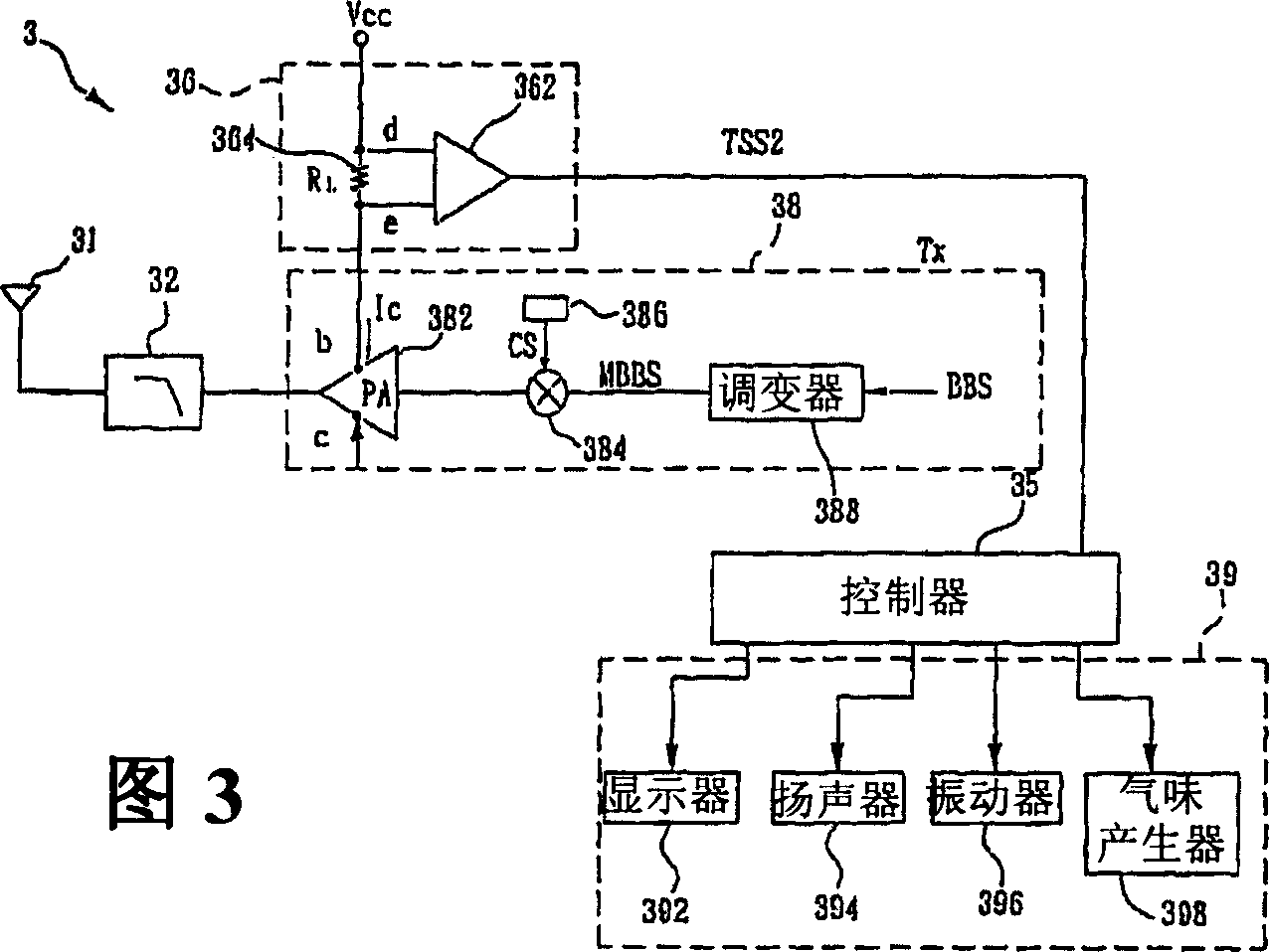
[0053] FIG. 3 is a block diagram of a second embodiment of a PCD with a radio frequency transmission power intensity indicating circuit according to the present invention. The transmit signal strength TSS can be determined by reading (sense) the direct current (DC) current consumption of the power amplifier 382 or directly reading the radio frequency signal power, as shown in FIG. 3 .
[0054] The transmit block 38 can generally be shown in FIG. 3 , which includes a modulator 388 , a power amplifier 382 and a radio frequency transmit power detector 36 . The transmitted baseband signal BBS is modulated in the modulation block 388 , and the modulated output signal MBBS is further processed and sent to the power amplifier 382 or directly sent to the power amplifier 382 . The signal is then sent to the filter 32 by the power amplifier 382, and finally sent to the antenna 31 for emission. A radio frequency transmit power detector (or called a transmit signal strength detector) i...
no. 3 example
[0065] Image 6 It is an operation flowchart for indicating the strength of the radio frequency transmission signal in the third embodiment of the present invention. The present invention provides a method for indicating the RF Transmit Signal Strength (TSS) of a transmitter to alert a PCD user of high RF radiation. The method includes the following steps:
[0066] (a) Preset an alarm intensity of the radio frequency transmission signal, as shown in step 602 . For example, taking dBm as the unit, the radio frequency radiation produced by a general GSM mobile phone has a power range from -5 to 33dBm. Figure 5 It is a schematic diagram of setting the alarm intensity of the radio frequency transmission signal in the third embodiment of the present invention. In this example, set 10dBm as the preset alarm intensity.
[0067] (b) As shown in step 604, detect TSS.
[0068] (c) In step 606, check whether the TSS is greater than or equal to the alarm intensity, if so, execute st...
PUM
 Abstract
Description
Claims
Application Information
 - R&D
- Intellectual Property
- Life Sciences
- Materials
- Tech Scout
- Unparalleled Data Quality
- Higher Quality Content
- 60% Fewer Hallucinations
Browse by: Latest US Patents, China's latest patents, Technical Efficacy Thesaurus, Application Domain, Technology Topic, Popular Technical Reports.
© 2025 PatSnap. All rights reserved.Legal|Privacy policy|Modern Slavery Act Transparency Statement|Sitemap|About US| Contact US: help@patsnap.com


