
Method of controlling time domain transmitting power envelope and its device

A technology for transmitting power and controlling time domain, which is applied in the control of components of amplifying devices, power amplifiers, and amplification control, etc., can solve problems such as complex circuit structures of baseband signal processing methods, save multiplier circuits, and be easy to design. The circuit achieves simple effects

Inactive Publication Date: 2005-05-25
SPREADTRUM COMM (SHANGHAI) CO LTD
View PDF0 Cites 1 Cited by
  • Summary
  • Abstract
  • Description
  • Claims
  • Application Information

AI Technical Summary

Benefits of technology

This new method allows for better quality signal transmission even if there may have problems due to imperfections or other factors affecting signals transmitted through an antenna interface (I). By completing the modulation process at both parts before sending data over wireless communication channels, fewer errors occur during reception compared to previous methods that had trouble controlling these issues. Additionally, saving on memory usage makes processing faster because less complex circuits could also work together more efficiently than older systems.

Problems solved by technology

This patented describes how long periods between two or three consecutive times when multiple people are sending data over wireless networks at once may cause them being unable to communicate without compromising any important features like timing synchronization. To solve this problem, some prior art methods involve generating specific waveforms for the base band signal beforehand, but these techniques have limitations because they require complex calculations involving various parameters during the overall process.

Method used


Image

  • Method of controlling time domain transmitting power envelope and its device
  • Method of controlling time domain transmitting power envelope and its device
  • Method of controlling time domain transmitting power envelope and its device

Examples


Embodiment Construction

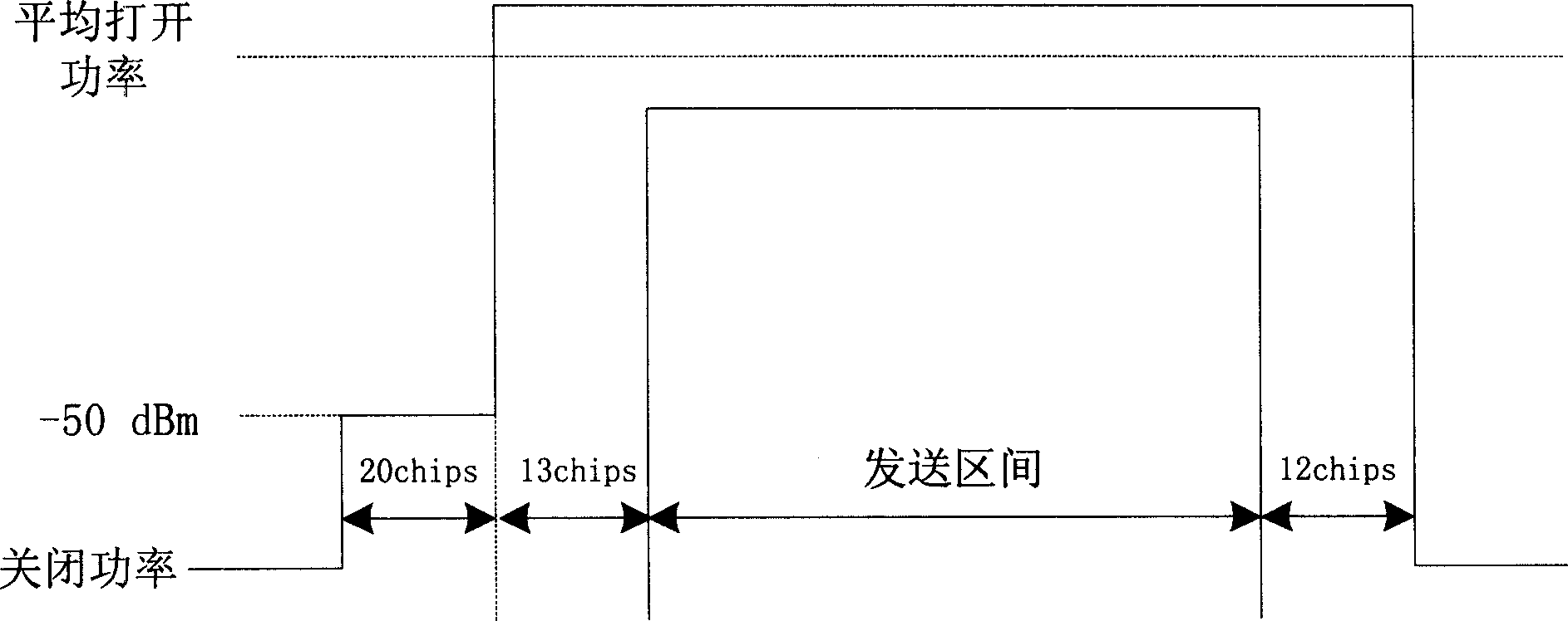
[0018] see Figure 4 , which is a structural schematic diagram of a device capable of realizing the method. As shown in the figure: it includes a baseband signal generator 1, a single-chip microcomputer 2 and a D / A converter 3 with a control signal memory 21 and a timer 22, wherein the baseband signal generator 1 provides a connection with the baseband signal while generating the baseband signal The synchronization signal corresponding to the baseband signal in time, the synchronization signal is connected to the IO port of the microcontroller 2 or the input of the interrupt signal, the microcontroller 2 detects the rising edge of the synchronization signal by polling or interrupting, and starts the built-in Timer 22, when the next change time is reached, the single-chip microcomputer sends the new control signal output value to the D / A converter 3 through the parallel port, and it is converted into an analog control signal; this process repeats until the last change time, Th...


PUM


Abstract

A method for controlling time domain transmitting power envelop contains directly transmit baseband signal to RF module, transmitting gain control signal wave synchronous with baseband signal in time to obtain control. Said device contains baseband signal generator, monolithic processor having control signal memory and timer, and D/A converter, wherein the memory is prestored change time and value of control signal, the baseband signal generator provides a synchronous signal corresponded with baseband signal at the same time to generate baseband signal, the synchronous signal is connected to IO port of monolithic processor which detects the rising edge of synchronous signal through polling or interruption, acting built in timer, monolithic processor transmits new control signal to D/A converter and converting it into analog control signal, let frequency spectrum of transmitted signal demand the power envelop.

Description


Claims


Application Information

Patent Timeline
Owner SPREADTRUM COMM (SHANGHAI) CO LTD
Learn More