


Quick Research
Generate reliable direction feasibility study reports for your R&D in just a few steps.

Technical Q&A
Discover and master advanced knowledge NOW. Basics, ideas, possibilities, all at once.

Find Solutions
As an expert in R&D theories, this can generate solutions to your technical problems instantly.

Evaluate Feasibility
Analyze your overall solution with one click, know your potential R&D risks in advance.

Monitor Landscape
Get weekly tech updates, stay abreast of the latest tech innovations and key insights.
Pressure connection structure with coaxial cable
A technology of coaxial cable and structure, applied in the direction of conductive connection, multi-core cable end parts, circuits, etc., can solve problems such as difficult installation to connectors
- Summary
- Abstract
- Description
- Claims
- Application Information
AI Technical Summary
Problems solved by technology
Method used
Image

Examples
no. 1 approach
[0054] (pierce terminal)
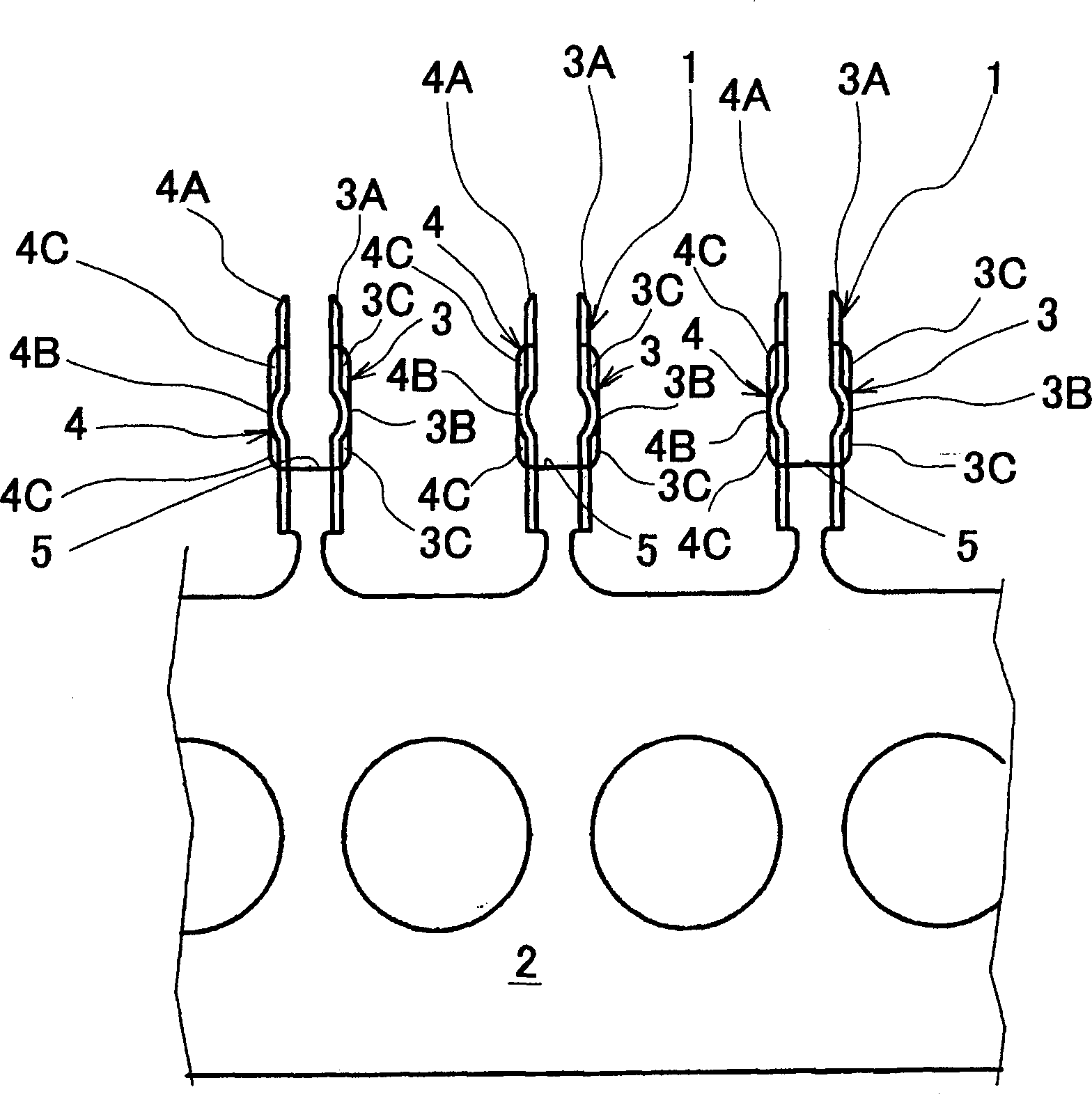
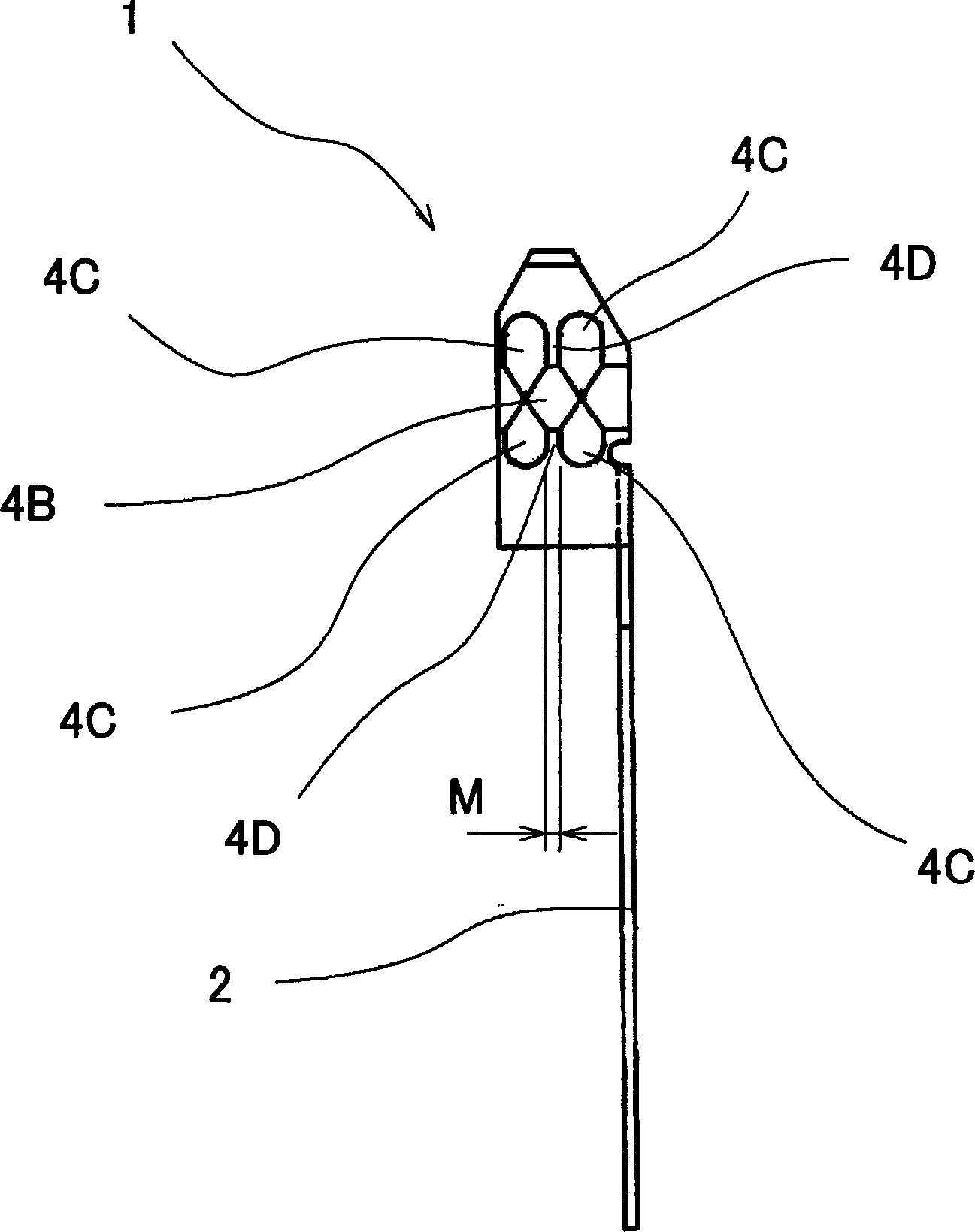
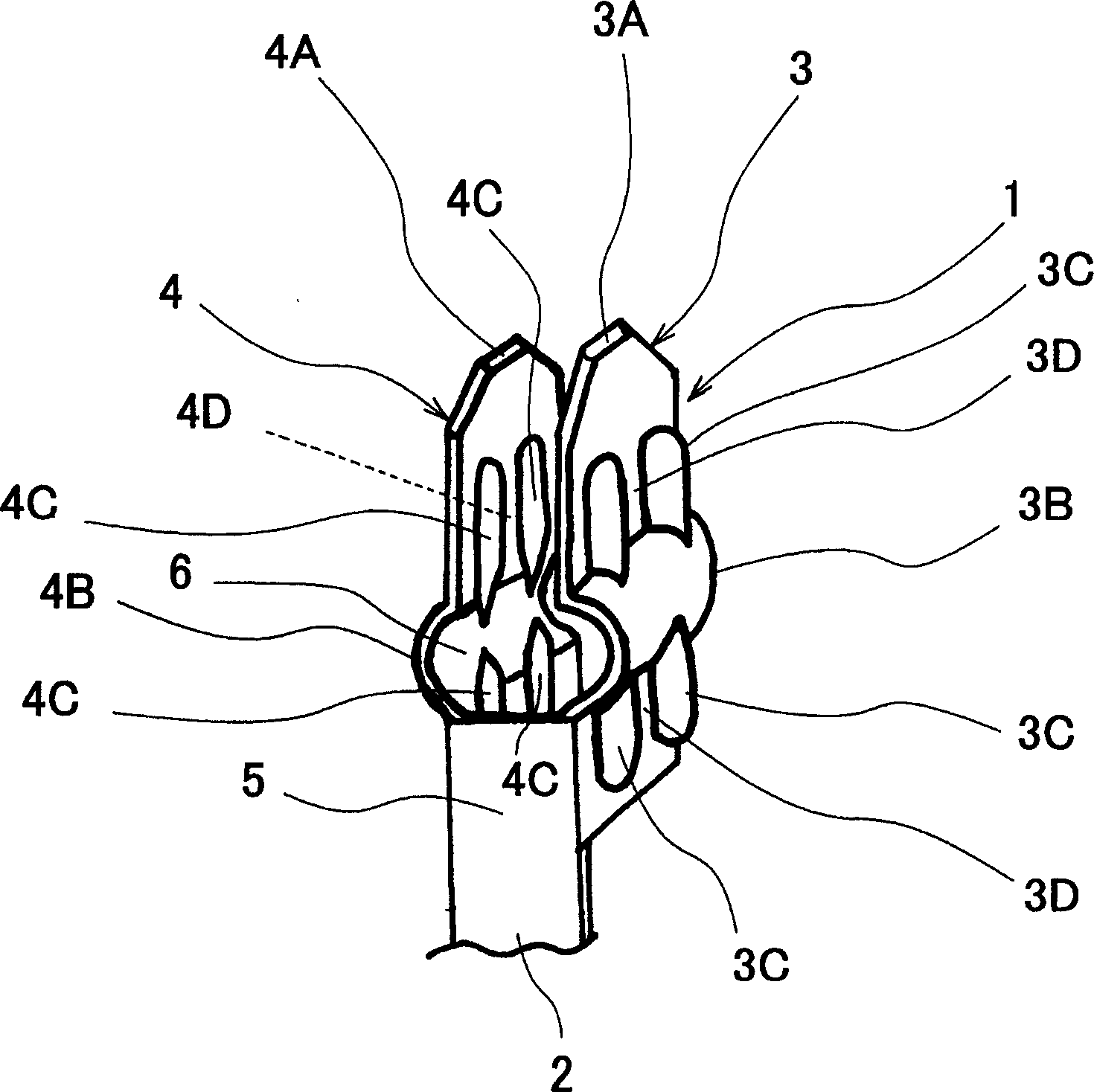
[0055] according to Figure 1-Figure 3 The structure of the piercing terminal related to the present invention will be described. figure 1 It is a front view during the manufacturing process of connecting a plurality of piercing terminals in a hoop state (continuously). figure 2 yes figure 1 side view. image 3 yes figure 1 Partial perspective view of .
[0056] The piercing terminal 1 is formed by cutting a strip-shaped metallic thin plate and performing processing such as punching and bending. Such as figure 1 As shown, a plurality of piercing terminals 1 , .
[0057] Then, if Figure 1-Figure 3 As shown, the piercing terminal 1 follows the coaxial cable 50 (for example, Figure 4 ) is crimped and inserted into the first case member 10 from the outside so that it is held in the case formed by the first case member 10 and the second case member. Through such insertion, the aforementioned through-hole terminal 1 is electrically connect...
no. 2 approach
[0102] according to Figure 18 - Figure 2 2. A second embodiment that is a modified example of the aforementioned first embodiment will be described. In this second embodiment, the structure in which the first case member 10 and the second case member 20 of the first embodiment are integrated is used as a male connector, and is connected to a female connector preliminarily mounted on the main circuit board by soldering. The combination is constituted in such a way that it can be freely combined and separated electrically.
[0103] exist Figure 18 - Figure 2 In 2, the same symbols are used for the same configuration, and repeated explanations are omitted, and primes are added to the symbols for similar configurations. Figure 18 The first housing member 10' and the second housing member 20' mean that although the shapes are different, each function is the same. Figure 18 It represents the housing composed of the first housing part 10' and the second housing part 20', which...
PUM
 Abstract
Description
Claims
Application Information
 - R&D Engineer
- R&D Manager
- IP Professional
- Industry Leading Data Capabilities
- Powerful AI technology
- Patent DNA Extraction
Browse by: Latest US Patents, China's latest patents, Technical Efficacy Thesaurus, Application Domain, Technology Topic, Popular Technical Reports.
© 2024 PatSnap. All rights reserved.Legal|Privacy policy|Modern Slavery Act Transparency Statement|Sitemap|About US| Contact US: help@patsnap.com