Master disk exposure apparatus and master disk exposure method
A technology of exposure device and exposure method, applied in the direction of recording/reproducing by optical method, optical recording/reproducing/erasing method, optical record carrier, etc. Problems such as signal intermodulation distortion
- Summary
- Abstract
- Description
- Claims
- Application Information
AI Technical Summary
Problems solved by technology
Method used
Image
Examples
specific example 1-1
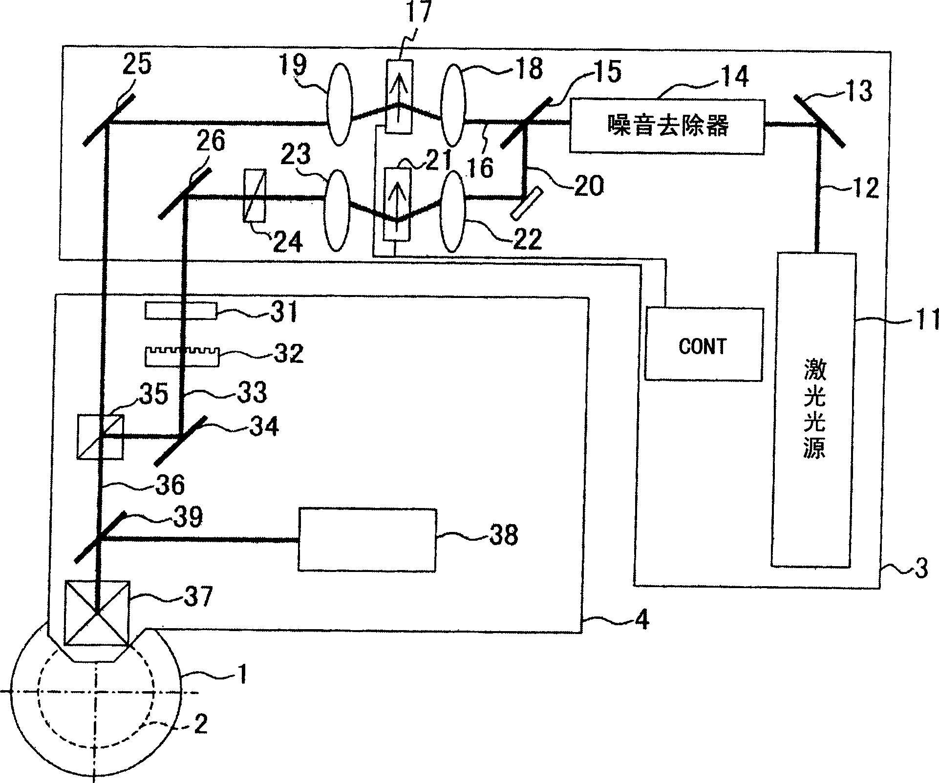
[0086] In the following, take an optical disc (disk) original disc exposure device, an optical disc (disk) original disc exposure method, and an optical disc (disk) substrate as examples, refer to Figure 1 ~ Figure 5 The master exposure device, master exposure method, and information recording substrate of the present invention will be described.
[0087] Such as figure 1 As shown, the optical disc (disk) original disc exposure device of this example is mainly composed of an optical disc (disk) original disc 1, a rotating table that drives the optical disc (disk) original disc 1 to rotate, a fixed table 3, and a fixed table fixed at a determined position. The moving table 4 arranged between the rotating table 2 and the fixed table 3 is configured.
[0088] The disk master 1 is formed by forming a photoresist layer of uniform thickness on the surface of a smooth disk-shaped substrate made of glass, for example.
[0089] Rotating table 2, such as figure 2 As shown, the above-menti...
specific example 1-2
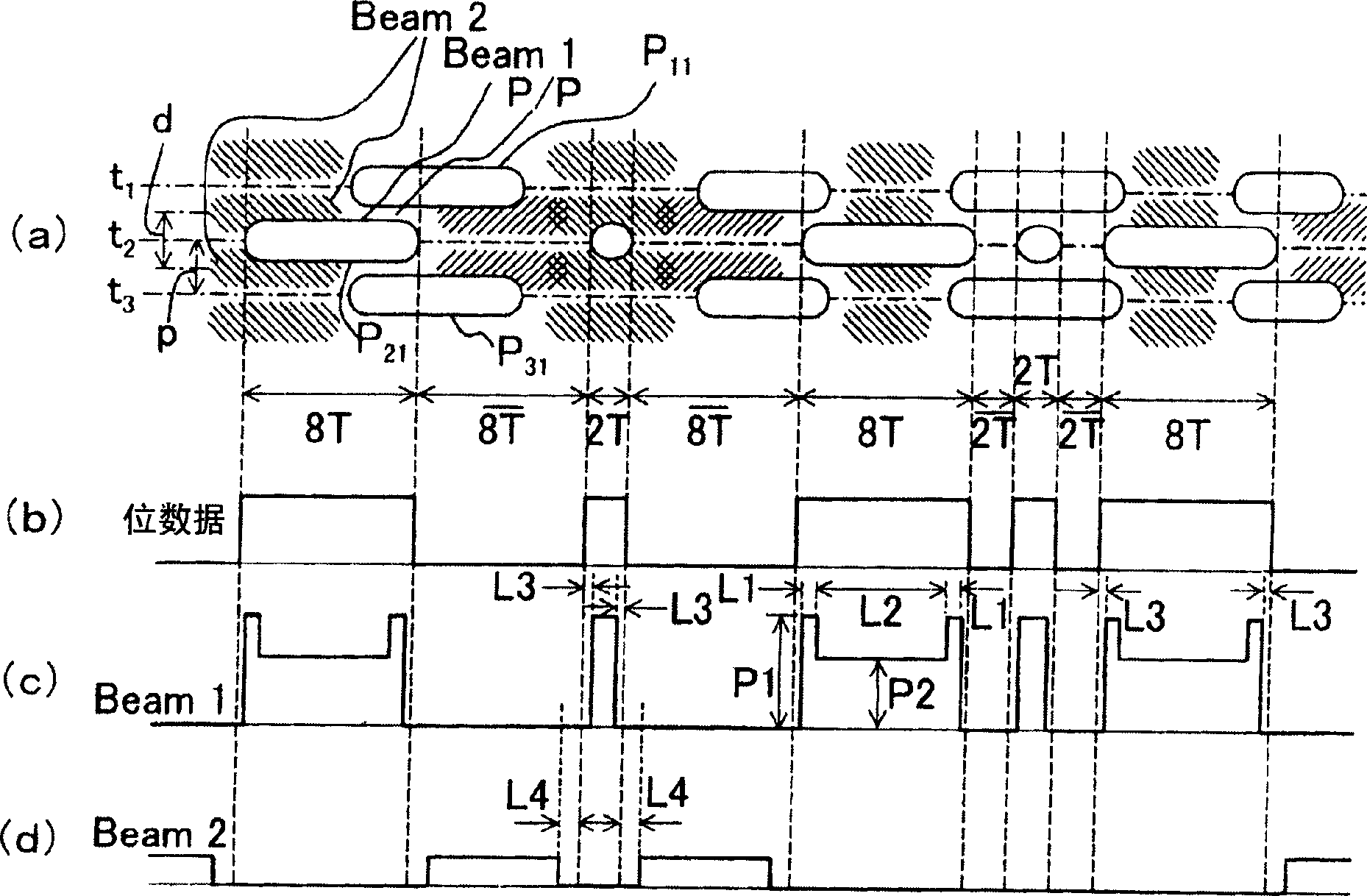
[0103] Figure 6 In [Specific Example 1-1], other specific examples of the master exposure method using the master exposure device are shown. In this example, except that the control device (CONT) of the master exposure apparatus changes the drive signal supplied to the second optical modulator, the exposure pattern diagram of the pit is formed in the same manner as in the specific example 1-1. Such as Figure 6 As shown in (a), in tracks t1 to t3, the same pit pattern diagrams as in [Specific Example 1-1] are formed respectively, and the bit data of track t2 is exposed ( Figure 6 (b)) and its beam waveform ( Figure 6 (c)) Same as [Specific Example 1-1]. However, regarding the beam (beam) 2, in [Specific Example 1-1], the pattern diagram opposite to the beam (beam) 1 is made, but in this example, as Figure 6 As shown in track t2 of (a), it is made: when the shortest groove (pit) P22 (length 2T) is irradiated with a beam (beam) 1, the area P / P (2T) on both sides of it is also i...
specific example 1-3
[0108] Figure 8 Shows another specific example of the master exposure method of the master exposure apparatus described in [Specific Example 1-1]. In this example, by switching the power of the laser beam (beam) to high intensity and low intensity, only a single laser beam (beam) is used based on [Specific Example 1-1] and [Specific Example] Irradiation of beam 1 and beam 2 in 1-2]. Specifically, in figure 1 In the master exposure apparatus shown, the driving of the second light modulator 21 is stopped, and the waveform in the first light modulator 17 is controlled by the controller (CONT), thereby irradiating Figure 8 The shown beam 2 has two types of power waveforms, high intensity and low intensity. Therefore, the trajectory of the beam, the high-intensity beam and the low-intensity beam are all in the center of the track (see track t2). In addition, in this example, the intensity P3 at the time of exposure of the shortest pit is set to be about 5% stronger than the intensi...
PUM
 Abstract
Description
Claims
Application Information
 - R&D
- Intellectual Property
- Life Sciences
- Materials
- Tech Scout
- Unparalleled Data Quality
- Higher Quality Content
- 60% Fewer Hallucinations
Browse by: Latest US Patents, China's latest patents, Technical Efficacy Thesaurus, Application Domain, Technology Topic, Popular Technical Reports.
© 2025 PatSnap. All rights reserved.Legal|Privacy policy|Modern Slavery Act Transparency Statement|Sitemap|About US| Contact US: help@patsnap.com


