
Optical element and method for its fabrication

A technology of optical components and optical components, applied in the direction of optical components, optics, optical devices, etc., can solve the problems of expensive glass and unusable types of objective glass

Active Publication Date: 2005-05-04
LEICA GEOSYSTEMS AG
View PDF2 Cites 3 Cited by
  • Summary
  • Abstract
  • Description
  • Claims
  • Application Information

AI Technical Summary

Problems solved by technology

However, this special glass is expensive and cannot be used in all glass types of objectives, such as flint glass

Method used


Image

  • Optical element and method for its fabrication
  • Optical element and method for its fabrication
  • Optical element and method for its fabrication

Examples


Embodiment Construction

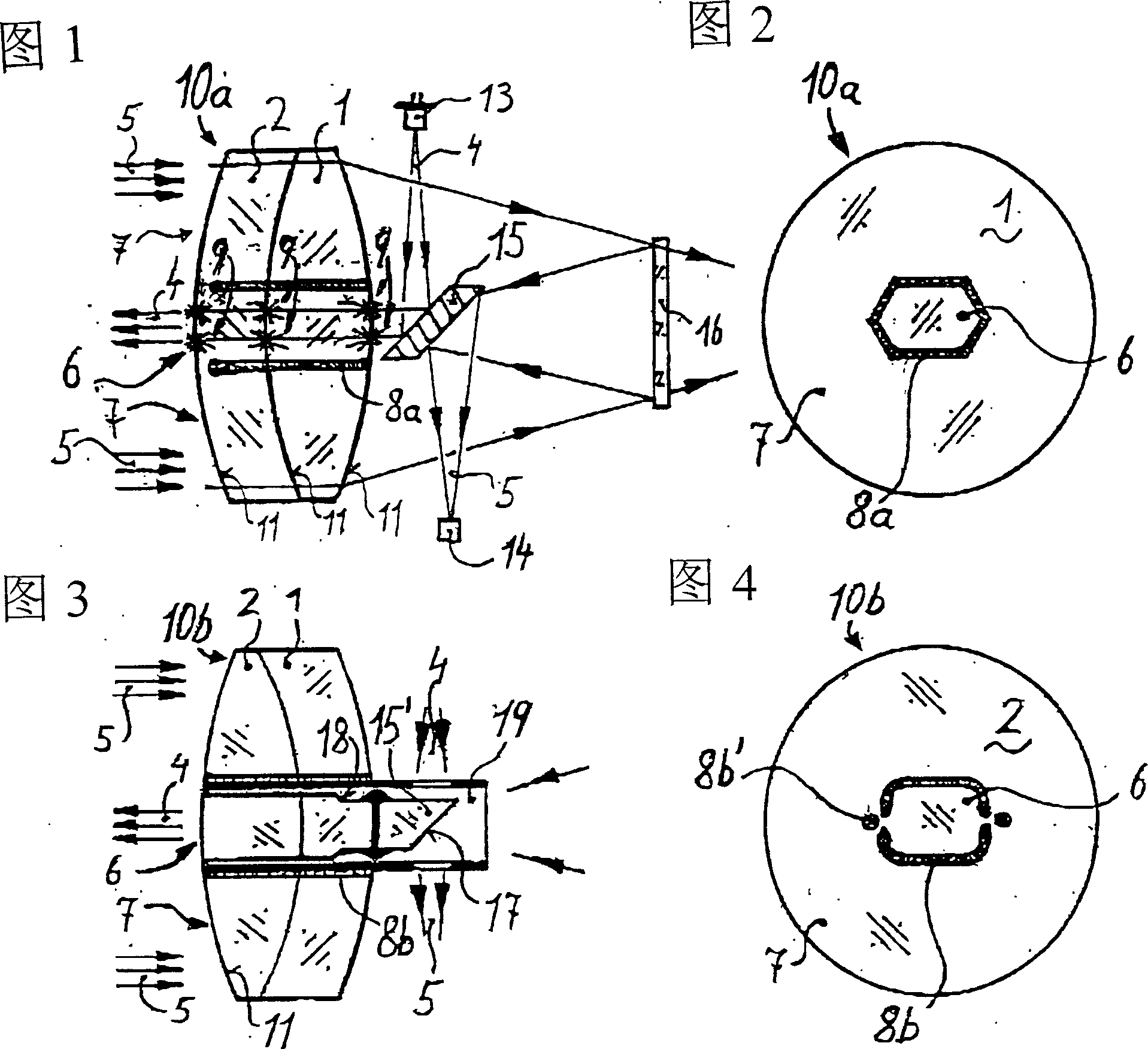
[0039] Fig. 1 shows a longitudinal sectional view of the lens barrel of the theodolite. Integrated in the lens barrel is a distance measuring device whose transmit and receive beams are coaxial with the line of sight. A first embodiment of an optical component according to the invention is a common objective 10a for both the line of sight of the lens barrel, the transmit and receive beams of the distance measuring device.

[0040] In known art, a column with such an arrangement also has an emitter 13, a receiver 14, an intermediate reflective element 15, a wavelength selective reflective element 16 and an eyepiece. The first light beam 4 as emitted light beam is generated here, for example, by a laser diode and has a hexagonal cross-section, which emerges from the emitter 13 and reaches the target not shown in FIG. 1 via the intermediate reflector element 15 . In this case, the intermediate reflector element 15 is positioned on the optical axis of the objective 10 a by means ...


PUM


Abstract

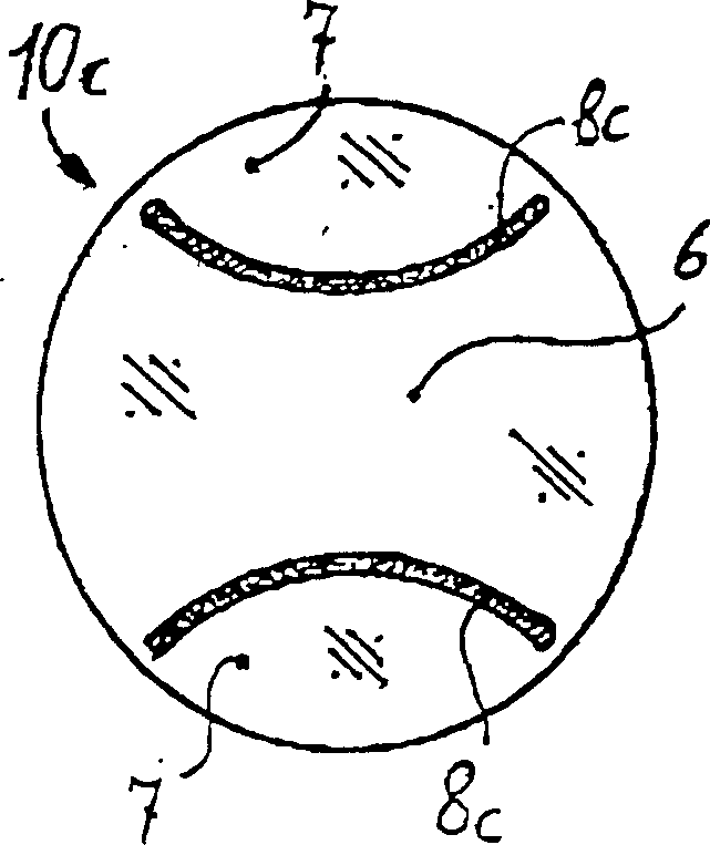
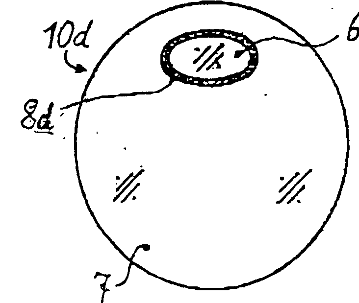
Optical component (10a) for a device for emitting a first beam cluster (4) and for receiving at least one second beam cluster (5) comprises a one-part element (1, 2) made of glass, quartz or another inorganic optical material with a first segment (6) refracting the first beam cluster and at least one second segment (7) refracting the second beam cluster. The first segment is surrounded by the second segment. A hollow (8a) is provided which surrounds the first segment and is designed so that, within the device, optical disturbances of scattered beams (9) of the first beam cluster with the second beam cluster are directly or indirectly prevented. Independent claims are also included for: (1) Device for distance measurement comprising the above optical component and a receiving beam cluster arranged coaxially to an emitting beam cluster; (2) Measuring instrument comprising the above distance-measuring device; (3) Alternative optical components; and (4) Processes for producing an optical component.

Description

technical field [0001] The invention relates to an optical component according to the preambles of claims 1, 15, 16 and 17 respectively, which component comprises an integral element made of glass, quartz or other inorganic optical material for at least two light beams, the invention It also relates to a distance measuring device and a measuring instrument according to the preambles of claims 13 or 14 and a method of manufacturing an optical component according to the preambles of claims 18 and 19 . Background technique [0002] Such optical components are components of many optoelectronic devices for measuring physical quantities or for recording, monitoring, regulating or controlling processes. The device emits a beam of light suitable for the respective application into the environment. The environment interacts with the emitted light beam and produces a received light beam that can be detected by the device. Since the manner of this interaction and the manner in which ...

Claims


Application Information

Patent Timeline
Patent Type & Authority Applications(China)
IPC IPC(8): G01B11/00G01C3/06G01C15/00
CPCG01C15/00
Inventor 海茵茨·伯恩哈德马塞尔·比尔基于尔格·欣德林
Owner LEICA GEOSYSTEMS AG
Learn More