Surge voltage suppressor

A surge voltage and suppression device technology, applied in circuit devices, emergency protection circuit devices, emergency protection circuit devices for limiting overcurrent/overvoltage, etc. problems, to achieve the effect of small installation site, prevention of insulation deterioration, and simple structure

Inactive Publication Date: 2005-03-09
FANUC LTD
View PDF1 Cites 3 Cited by
  • Summary
  • Abstract
  • Description
  • Claims
  • Application Information

AI Technical Summary

Problems solved by technology

[0006] However, in the method of suppressing the surge voltage by using a filter composed of a reactor and a capacitor, there is a problem that the space required for installing the filter device needs to be enlarged, so the cost is high.
[0007] In addition, in the method disclosed in the aforementioned Japanese Patent Laid-Open No. 8-23682 that absorbs the surge voltage into the capacitor through the three-phase diode bridge, there is a problem that current always flows through the resistor, and energy is consumed in vain.

Method used


Image

  • Surge voltage suppressor
  • Surge voltage suppressor
  • Surge voltage suppressor

Examples


Embodiment Construction

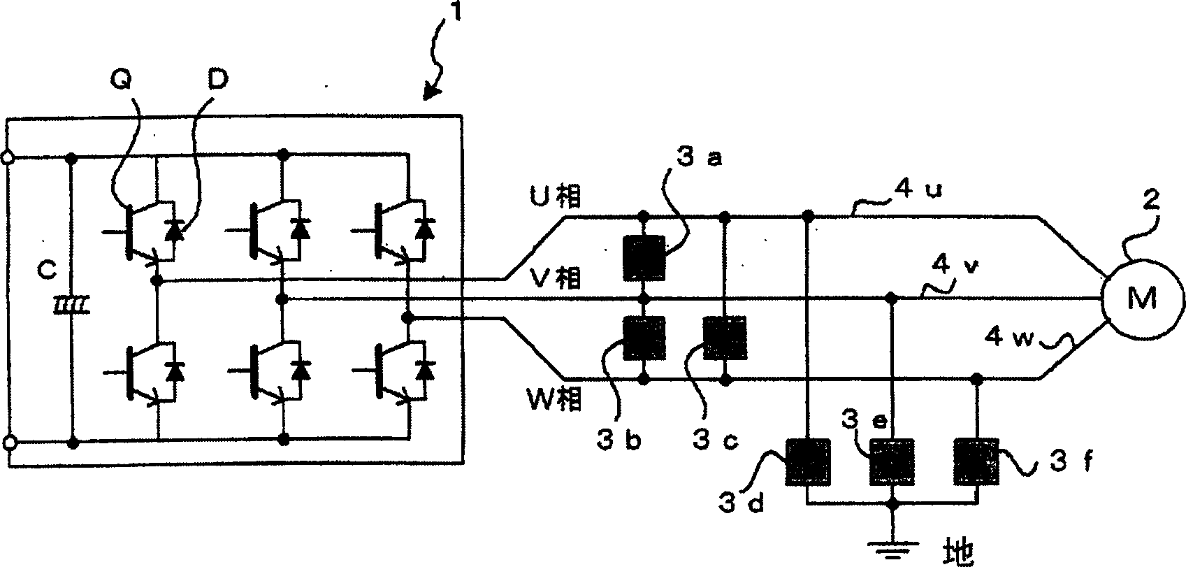
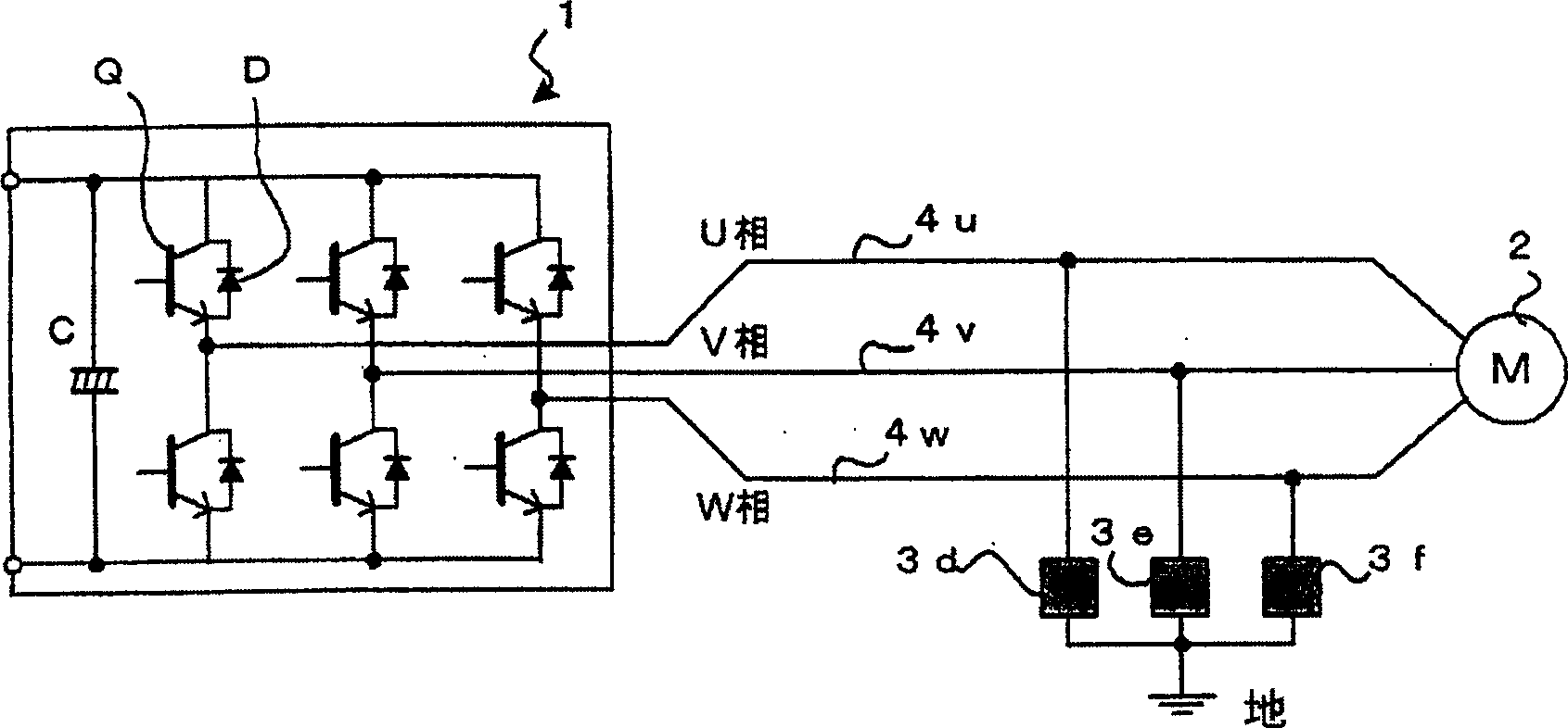
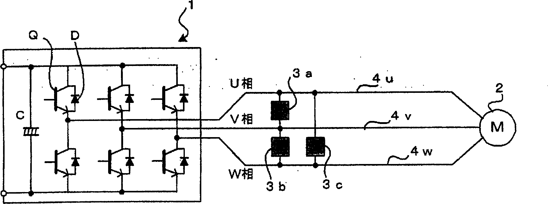
[0023] figure 1 It is a block diagram of main parts of the first embodiment of the present invention.

[0024] Symbol 1 is an inverter for converting DC voltage into AC voltage by PWM control, which is a conventionally known device. A pair of a switching element Q such as a power transistor and a diode D connected in parallel is connected in series between the positive and negative terminals of the DC power supply in each phase of U, V, and W. Outputs from the respective phases of the inverter 1 are taken out from series connection points of pairs of switching elements such as power transistors Q and diodes D connected in parallel, and are respectively connected to terminals of the motor 2 via power lines 4u, 4v, and 4w. Coils for U, V, and W phases. Furthermore, the symbol C in the inverter 1 is the capacitance of the DC power supply.

[0025] Then, semiconductor surge absorbing elements 3 ( 3 a to 3 f ), which have the characteristics of flowing current and clamping the v...


PUM


Abstract

Semiconductor surge absorbing devices are connected individually between power lines for the U, V and W phases, which connect an inverter and a motor, and between the ground and the power lines. The absorbing devices are adapted to be energized to clamp voltages between opposite terminals thereof when the voltages are higher than a given value.

Description

technical field [0001] The present invention relates to a surge voltage suppression device for controlling a surge voltage generated in a motor when the motor is controlled by an inverter PWM. Background technique [0002] In the case where the inverter PWM (pulse width modulation) is used to control the motor for drive control, it is the switching of switching elements such as power transistors controlled by PWM, which generates AC voltage from DC voltage and applies the AC voltage to each phase of the motor. On the coil, to drive and control the motor. [0003] In the case of PWM control of such a motor, since the switching element ON / OFF is used to control the DC voltage, if the power line connected to the motor is long, the inductance of the power line becomes large, and the 3-phase in the motor Surge voltages are generated between the coils and between the 3-phase coils and ground. There is a problem that the insulation between the three-phase coils in the motor and b...

Claims


Application Information

Patent Timeline
Patent Type & Authority Applications(China)
IPC IPC(8): H02H7/08H02H9/04H02M1/00H02M7/48
CPCH02H9/042H02H7/0838
Inventor 松原俊介君岛正巳山田裕一
Owner FANUC LTD
Why Eureka
Try Eureka