
Method and equipment for continuous production of rolled metal plate from molten metal

A technology of metal strips, molten metal, applied in the direction of metal rolling, metal rolling, metal rolling stands

Inactive Publication Date: 2005-02-02
VOEST ALPINE AG
View PDF2 Cites 7 Cited by
  • Summary
  • Abstract
  • Description
  • Claims
  • Application Information

AI Technical Summary

Problems solved by technology

However, this is only possible on a limited transport segment

Method used


Image

  • Method and equipment for continuous production of rolled metal plate from molten metal
  • Method and equipment for continuous production of rolled metal plate from molten metal
  • Method and equipment for continuous production of rolled metal plate from molten metal

Examples


Embodiment Construction

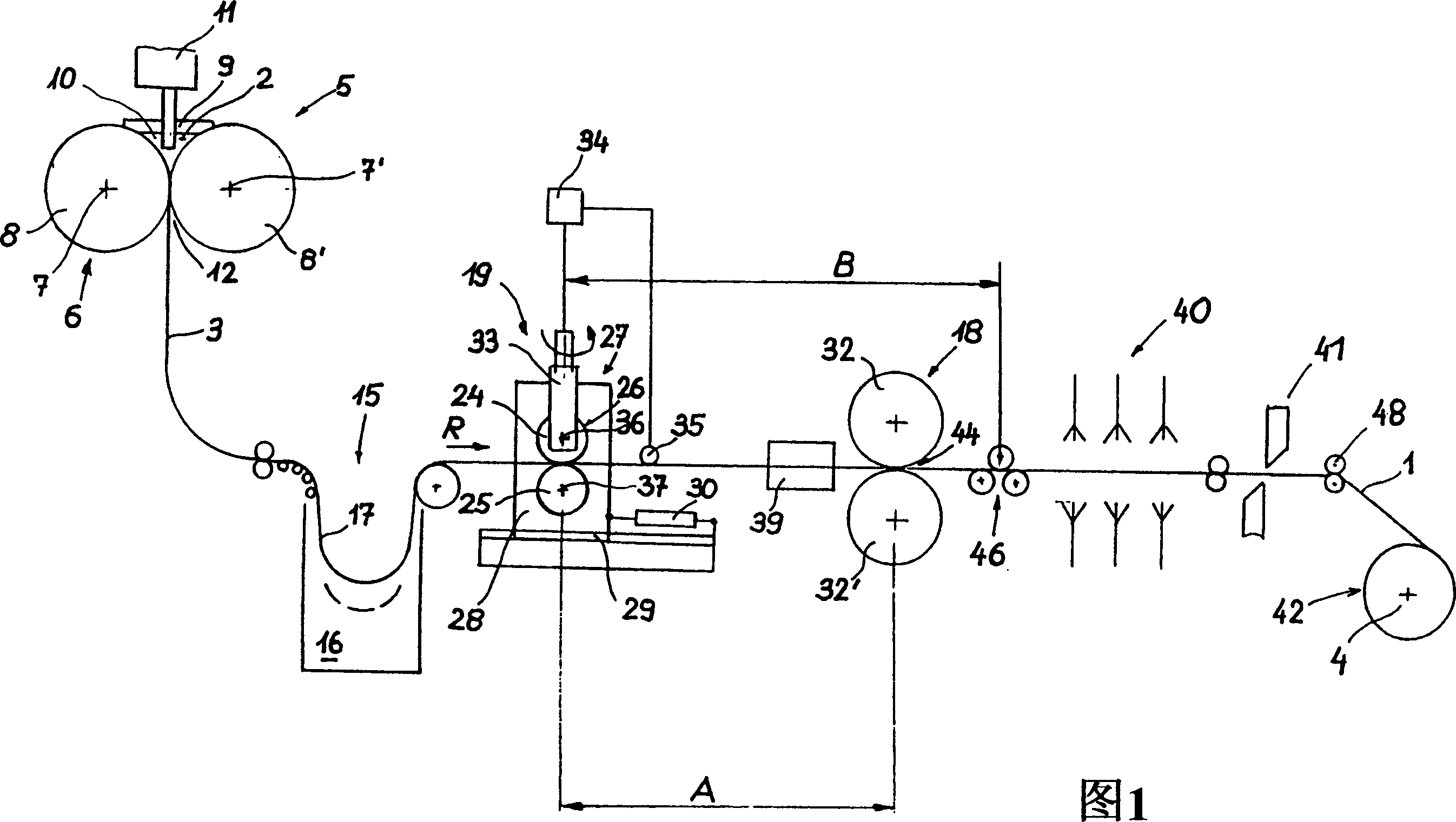
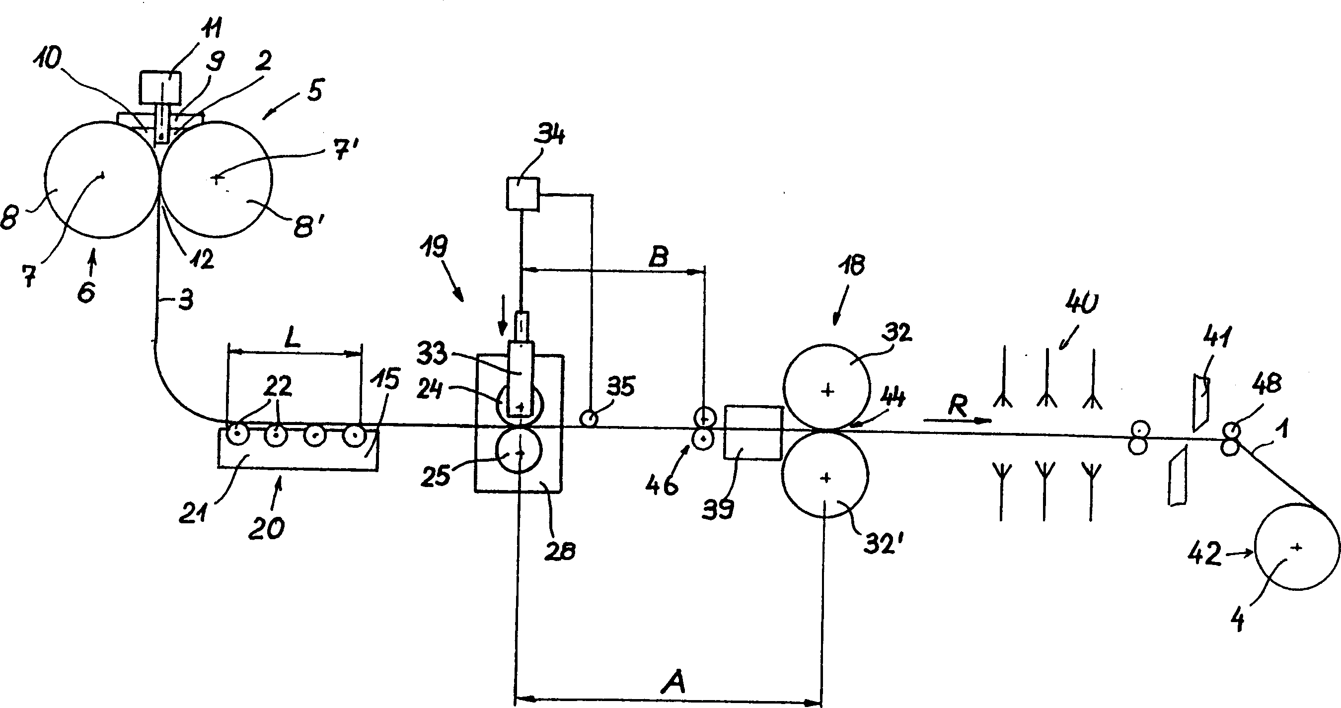
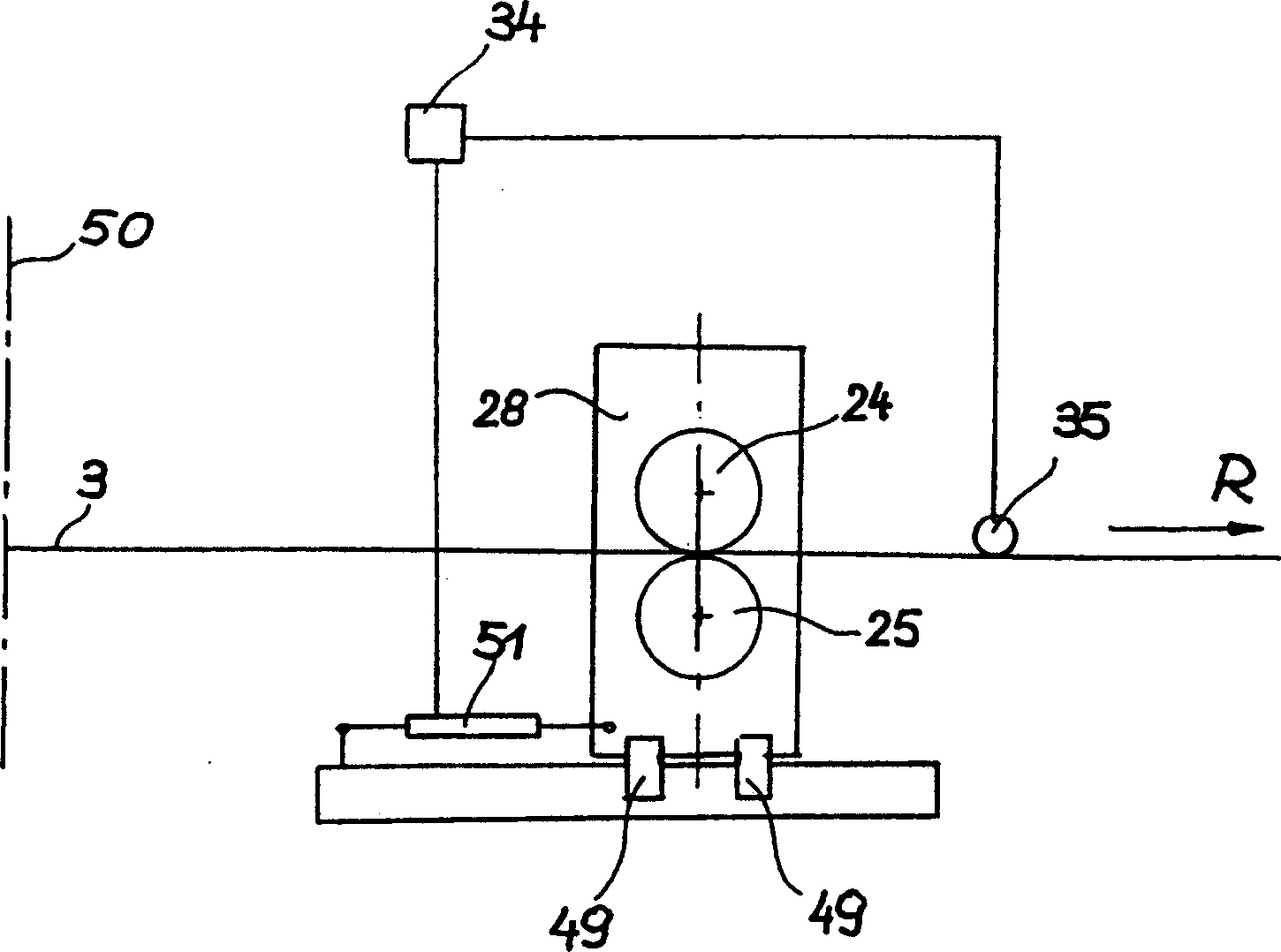
[0029]In the embodiment shown in Figures 1 to 3, which are described below, like reference numerals designate like elements. 1 and 2 show a plant according to the invention for the continuous production of rolled metal strip 1 with molten metal 2, wherein, in a first production step, cast metal strip 3 is produced from molten metal, and in the next In a second production step of one step, the cast metal strip 3 is thermally deformed during rolling. If appropriate, after a controlled cooling process, which is not explained further in the context of the present invention, the rolled metal strip 1 produced in this way is subsequently coiled into coils 4 of predetermined weight.

[0030] The strip casting device 5 is used to produce strip casting metal strips with a thickness between 1.0 mm and 20 mm. The stream forming core unit of the device is composed of a single belt moving horizontally on the lower side, or multiple turnover belts, caterpillars Or cast wall composition,. F...


PUM

PropertyMeasurementUnit
thicknessaaaaaaaaaa
thicknessaaaaaaaaaa

Abstract

The invention relates to a method and to a device for producing a rolled metal strip from a molten metal by producing a cast metal strip in a strip casting device (5) and then rolling the undivided metal strip in a roll stand (18) to the final thickness of the strip. For controlling the course of the strip, strip guiding devices (19) are provided, especially upstream of the roll stand. In order to guarantee, with little components required, a stable insertion of the metal strip into the roll stand at the input side of the roll stand or at the site of rolling in accordance with the strip dimensions, the strip guidance interferes or is carried out at a distance of 1.0 to 10.0 times the strip width, preferably at a distance of 1.5 to 5.0 times the strip width, upstream of the roll stand.

Description

technical field [0001] The present invention relates to a method for the continuous production of rolled metal strip, in particular steel sheets, from molten metal, wherein in a first production step the molten material is introduced into a strip casting device with a thickness of less than 20 mm, preferably between 1 mm and 12 mm , and the cast metal strip with a predetermined width will be removed from the strip casting device, and in the subsequent second production step, the cast uncut metal strip will be rolled and deformed in at least one stand until reaching At its final plate thickness, the metal strip is positioned in the roll nip by strip deflectors installed upstream of the stand. The invention also relates to a device for carrying out the method, and a method for activating the device. Background technique [0002] Such methods and corresponding plants for producing rolled steel plates from molten steel are known from EP-B 540 610 and EP-A 760 397, where thin ca...

Claims


Application Information

Patent Timeline
Patent Type & Authority Applications(China)
IPC IPC(8): B21B1/00B21B1/46B21B13/22B21B37/48B21B37/68B21B39/00B21B39/08B21B39/12B21B39/14B21B39/16B21B41/08B21B45/00B22D11/06B22D11/12
CPCB21B1/463B21B39/08B21B39/006B21B41/08B21B45/004B21B37/48B21B39/12B21B37/68Y10T29/49991B21B1/46
Inventor 格拉尔德·霍恩比希勒格拉尔德·埃克尔斯托弗
Owner VOEST ALPINE AG
Learn More