Method for exciting light for optical amplification medium fiber, structure for emitting excited light into optical amplification medium fiber optical fiber amplifier, and uses

A technology of optical amplification and excitation light, applied in the fields of fiber lasers, fiber amplifiers and fiber lasers, it can solve the problems of inability to output laser light, transparency damage, structure burning, etc., so as to improve the incidence efficiency, reduce costs, and reduce parts The effect of the number of pieces

Inactive Publication Date: 2005-02-02
THE FUJIKURA CABLE WORKS LTD
View PDF4 Cites 1 Cited by
  • Summary
  • Abstract
  • Description
  • Claims
  • Application Information

AI Technical Summary

Problems solved by technology

When the excitation light introduction part burns out, the excitation light is not introduced into the rare earth-doped fiber, the oscillation of the excitation light in the rare earth-doped fiber stops, and there is a problem that laser light cannot be output.
[0027] On the other hand, for the method of introducing the excitation light from the side of the double-clad fiber, since the excitation light is transmitted in a transverse manner in a plurality of optical fibers, the transmission attenuation and scattering of the excitation light occur in the gap between the fibers. loss
[0028] In order to prevent such transmission attenuation and scattering loss, the optical fiber is embedded in an organic adhesive, but the light resistance of the organic adhesive is low
When the intensity of the excitation light is increased to obtain a high-output laser, the organic binder is modified, the transparency is impaired, and the mechanical strength is reduced, so the output power of the laser is often extremely reduced.
In addition, sometimes the whole structure composed of multiple optical fibers is burned, and the laser light cannot be output.

Method used


Image

  • Method for exciting light for optical amplification medium fiber, structure for emitting excited light into optical amplification medium fiber optical fiber amplifier, and uses
  • Method for exciting light for optical amplification medium fiber, structure for emitting excited light into optical amplification medium fiber optical fiber amplifier, and uses
  • Method for exciting light for optical amplification medium fiber, structure for emitting excited light into optical amplification medium fiber optical fiber amplifier, and uses

Examples


Embodiment Construction

[0072] Hereinafter, the present invention will be described in detail based on embodiments.

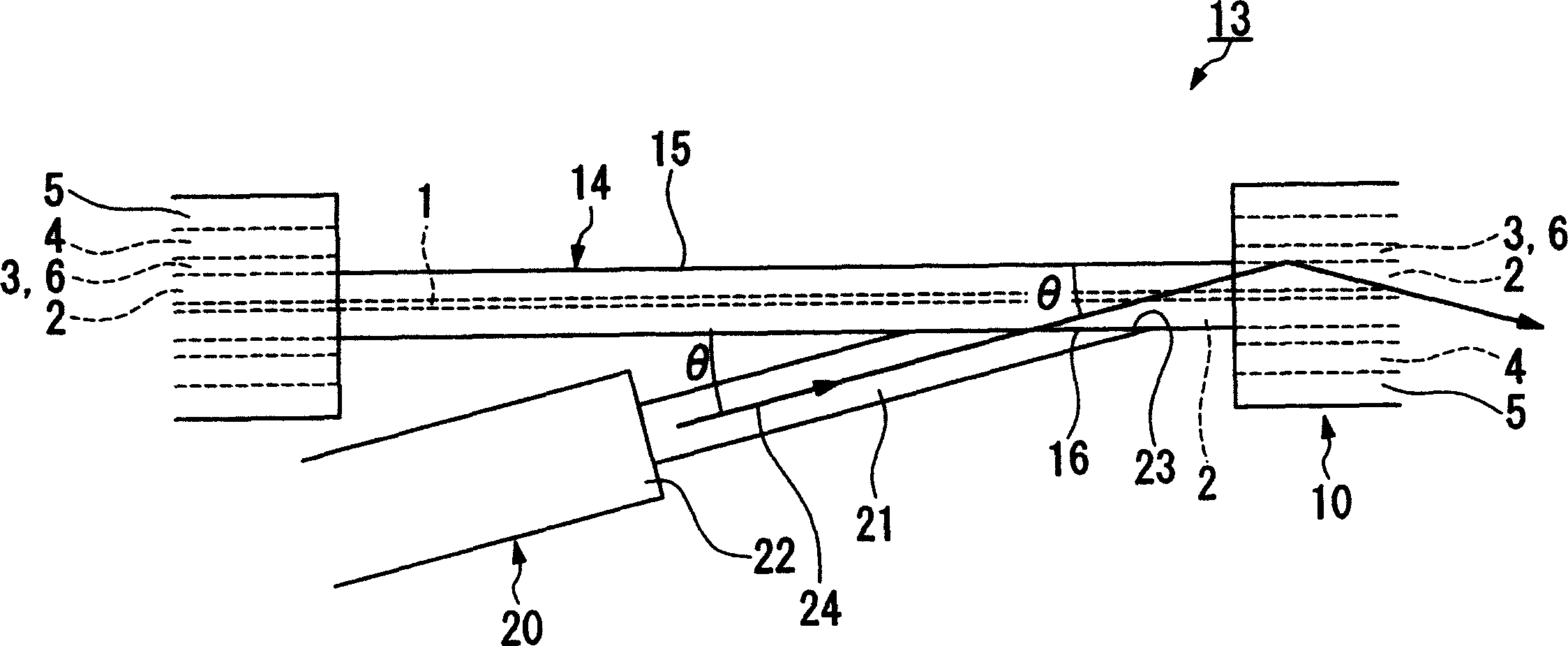
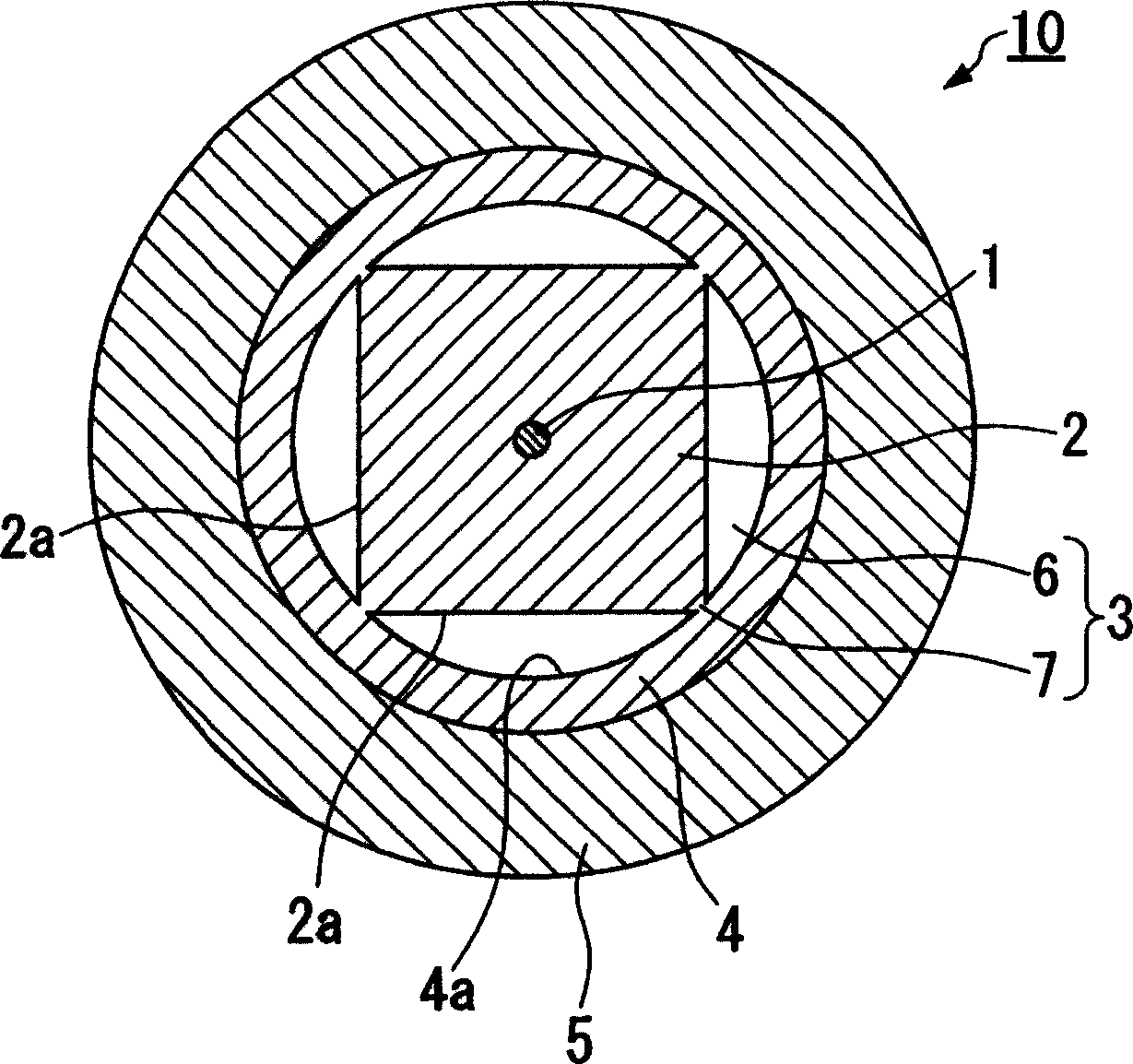
[0073] figure 1 It is a schematic configuration diagram showing an embodiment of an excitation light incident structure (hereinafter often simply referred to as an "excitation light incident structure") to an optical amplifying medium fiber of the present invention. in addition, figure 2 yes means figure 1A cross-sectional view of the light-amplifying dielectric fiber used in the excitation light incident structure shown.

[0074] Such as figure 2 As shown, the optical amplifying dielectric fiber 10 used in the excitation light incident structure of this embodiment has: a core 1 to which a rare earth element is added, an inner cladding 2 provided on the outer periphery of the core 1, and an inner cladding 2 on the inner cladding. A void layer 3 formed on the periphery of the layer 2 , an outer cladding layer 4 provided on the periphery of the void layer 3 , and a cover layer 5...


PUM


Abstract

An inner clad exposure (14) where an inner clad (2) is exposed is formed by removing a part of an outer clad (4) in a longitudinal direction in the optical amplification medium fiber (10) having a hole layer (3) between the inner clad (2) and the outer clad (4). An end face (23) of the optical fiber for excited light incidence (20) is bonded (bonding part (16)) to an outer periphery (15) of the exposed inner clad (2), and excited light (24) is made incident on the optical amplification medium fiber (10) from the optical fiber for excited light incidence (20). Such excited light incident structure (13) is used for incidence of excited light of the optical fiber amplifier and the optical fiber laser. To provide a photoexciting method of an optical amplification medium fiber, with which excited light can highly efficiently be made incident on the optical amplification fiber and a superior amplification characteristic can be obtained, and to provide an excited light incident structure to the optical amplification medium fiber, an optical fiber amplifier and an optical fiber laser.

Description

[0001] The invention of this application is based on Japanese Patent Application No. 2003-151260 (applied on May 23, 2003) and Japanese Patent Application No. 2003-179850 (applied on June 24, 2003) at the Japan Patent Office, and incorporates the contents thereof application for the invention. technical field [0002] The invention relates to an optical excitation method of an optical amplifying medium fiber used in the fields of information communication, laser medical treatment, and laser processing, an excitation light incident structure for the optical amplifying medium fiber, an optical fiber amplifier and an optical fiber laser. [0003] Additionally, the invention relates to fiber lasers. Background technique [0004] In the past, as a kind of optical amplification medium fiber, such as Figure 12 As shown, an inner cladding layer 102 is provided on the outer periphery of a core 101 to which rare earth elements are added, an outer cladding layer 104 is provided on the...

Claims


Application Information

Patent Timeline
Patent Type & Authority Applications(China)
IPC IPC(8): H01S3/067H01S3/094
CPCH01S3/06708H01S3/094003
Inventor 岛研介北林和大酒井哲弥
Owner THE FUJIKURA CABLE WORKS LTD
Why Eureka
Try Eureka