Road indication device
A technology for displaying devices and roads, applied to display devices, roads, roads, etc., can solve the problems of being seen by people, limited color of laser light, and small degree of freedom of choice, so as to prevent disability glare and discomfort glare, and prevent discomfort Glare and disability glare, the effect of increasing the freedom of color selection
- Summary
- Abstract
- Description
- Claims
- Application Information
AI Technical Summary
Problems solved by technology
Method used
Image
Examples
Embodiment 1
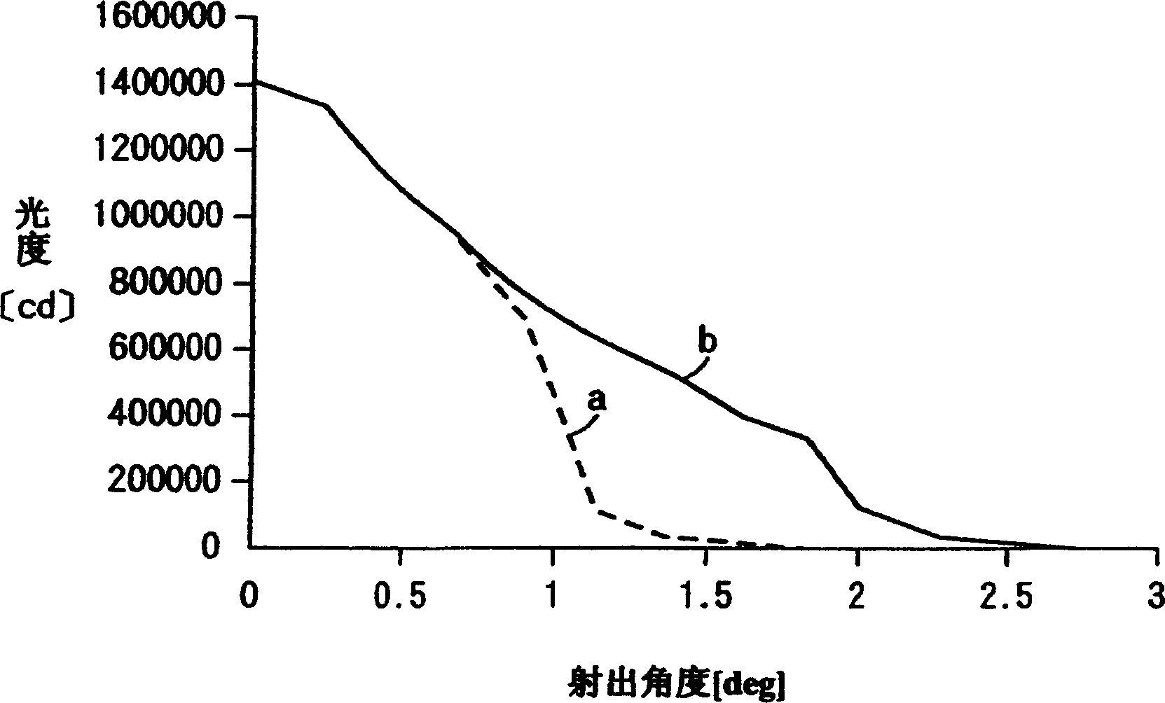
[0132] Next, one embodiment of the present invention will be described with reference to the drawings. Figure 1 to Figure 5 Representing the first embodiment, Fig. 1 is an explanatory diagram of the use state of the road guidance display device, and Fig. 2 is a structural diagram of the road guidance display device, image 3 It is an explanatory diagram of the state of use of the road guidance display device installed at regular intervals on the road, Figure 4 It is a graph showing the light distribution of the road guidance display device, Figure 5 It is an explanatory diagram showing the vertical angle of 90° and the vertical angle of 80° of the road guidance display device.
[0133] As shown in FIG. 2, the road guidance display device 11 includes a housing 13 having a light projection opening 12 for projecting light toward one end in the direction of the optical axis. In the housing 13, a light source such as a metal halide lamp is accommodated. , a halogen lamp, a lam...
Embodiment 2
[0161] Additionally, if Image 6 As shown in the second embodiment of , by bending the reflective part 32a from the edge of the arrow-shaped symbol part on the lower end side of the arrow-shaped mark 32 toward the surface side on which the light 22 is irradiated, the reflection reflected by the reflective part 32a Irradiating the surface of the arrow-shaped mark 32 with light can make the arrow-shaped mark 32 brighter and further improve its visibility.
[0162] In addition, it is also possible to adopt a configuration in which the projection direction of the light 22 of the road guidance display device 11 is controlled by the control unit 23 to switch and move between the direction of the road surface 27a and the direction of the arrow-shaped mark 32 according to the time zone or the like. . For example, by projecting the light 22 of the road guidance display device 11 on the road surface 27a under normal circumstances, and in the late night time period when there is little ...
Embodiment 3
[0164] The third embodiment is as Figure 7 As shown, the arrow-shaped logo 32 has a long base 34 and a slightly triangular arrow-shaped symbol 35 connected to the lower end of the base 34 along the up-down direction. These bases 34 and arrow-shaped symbol 35 are bent to form a The central part of the surface opposite to the surface on which it is installed is a convex convex surface.
[0165] On the surface of the base portion 34 mounted on the light projecting portion 21, a rail 37 having a groove portion 36 with a slightly grooved cross-section is installed in the up-down direction, and the groove portion 36 of the rail 37 is slidably engaged and fixed. The fastening device 38 including bolts or the like provided at two positions above and below the side surface of the light projecting part 21 can adjust the position of the arrow-shaped mark 32 in the vertical direction of the light projecting part 21 .
[0166] A bracket 39 for mounting on the pillar 31 is attached to the...
PUM
 Abstract
Description
Claims
Application Information
 - R&D
- Intellectual Property
- Life Sciences
- Materials
- Tech Scout
- Unparalleled Data Quality
- Higher Quality Content
- 60% Fewer Hallucinations
Browse by: Latest US Patents, China's latest patents, Technical Efficacy Thesaurus, Application Domain, Technology Topic, Popular Technical Reports.
© 2025 PatSnap. All rights reserved.Legal|Privacy policy|Modern Slavery Act Transparency Statement|Sitemap|About US| Contact US: help@patsnap.com


