Three-cavity packaging shield box for microwave filter and method for producing same

A microwave filter and filter technology, which is applied to waveguide devices, electrical components, circuits, etc., can solve the problems of inconvenient design and production, inconsistent welding, and low filter yield, so as to reduce adverse effects and improve product quality. efficiency, solve the effect of difficult assembly

Inactive Publication Date: 2005-01-26
海泰超导通讯科技(天津)有限公司
View PDF0 Cites 5 Cited by
  • Summary
  • Abstract
  • Description
  • Claims
  • Application Information

AI Technical Summary

Problems solved by technology

[0002] For microwave filters, the size and shape of the inner cavity of the packaging box and the welding and assembly of the filter working pieces will have a greater impact on the performance of the filter. However, microwave design software is currently being used to analyze the frequency characteristics of the filter. In computer simulation, generally only the planar circuit structure of the filter work piece can be simulated, and it is difficult to carry out quantitative and accurate calculation of the welding points of the filter work piece, but often the welding inconsistency of the welding point part causes the filter The performance of the filter deteriorates, resulting in a low yield of the filter
At the same time, within the operating frequency range of the microwave filter, the applied 50 ohm port matching impedance has strict requirements on the width of the microstrip transmission line, so the size and position of the solder joints of the filter work piece are subject to greater influence. The limitation caused great inconvenience to both design and production

Method used


Image

  • Three-cavity packaging shield box for microwave filter and method for producing same
  • Three-cavity packaging shield box for microwave filter and method for producing same
  • Three-cavity packaging shield box for microwave filter and method for producing same

Examples


Embodiment

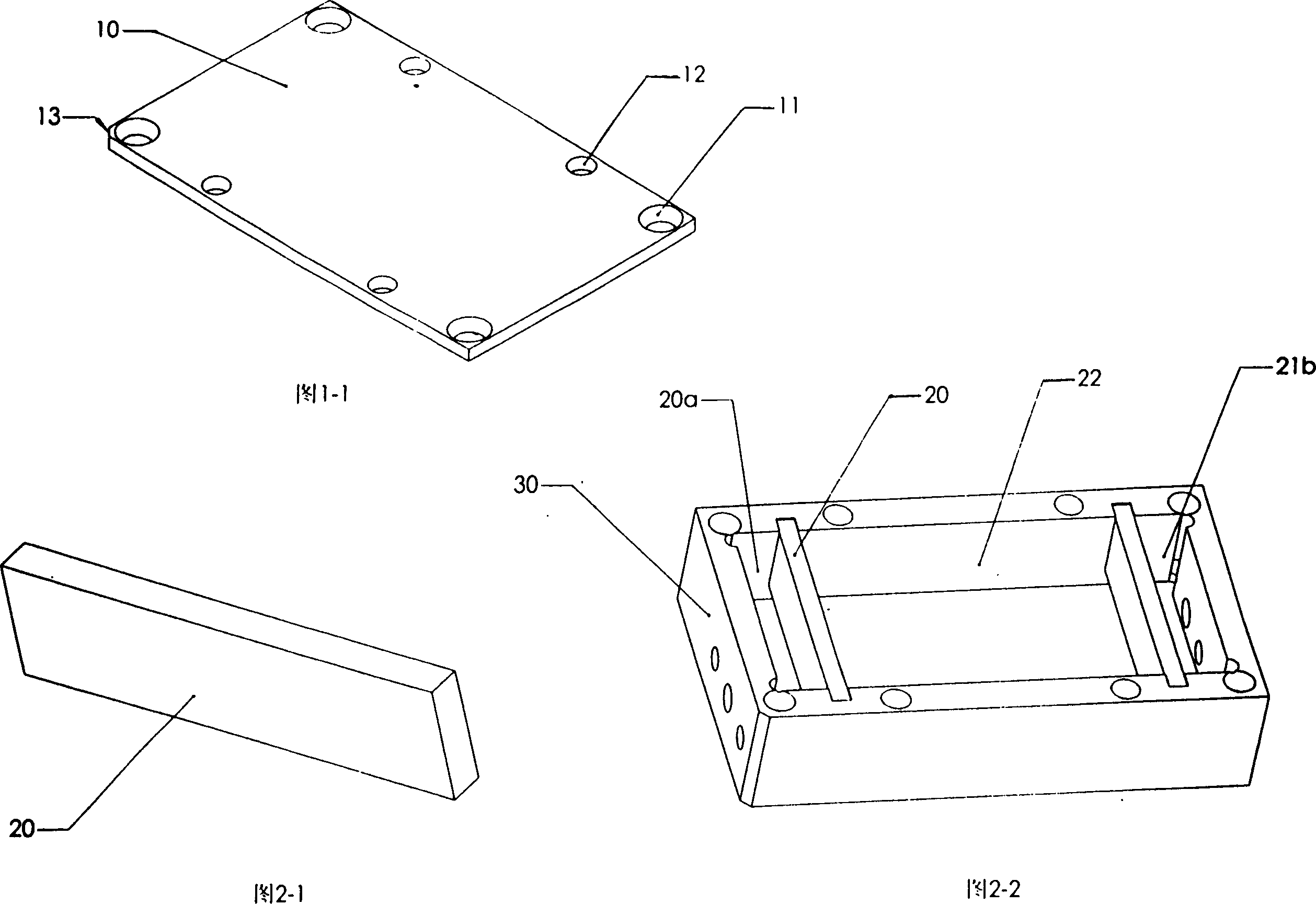
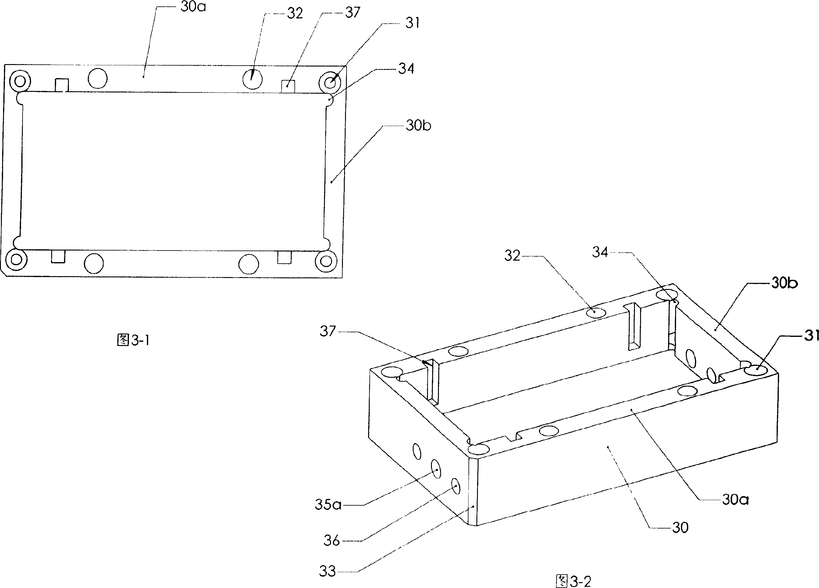
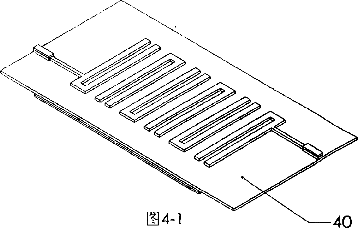
[0024] Embodiment: A microwave filter three-cavity package shielding box (see Figure 1-1~ Figure 5-2 ), including box cover 10, filter box base 30, filter work piece 40 and standard SMA joint 51, it is characterized in that on the filter box base 30, two insertable filter activities are assembled according to the positioning slot 37 The shielding partition 20 and the box base 30 are symmetrically separated by the movable shielding partition 20 of the two filters into a three-cavity packaging shielding box (see Fig. 2-2); Circuit 42, working sheet dielectric layer 43, working sheet bottom superconducting material layer 44, working sheet bottom gold-plated layer 45 constitute the filter working sheet 40 in sequence, the superconducting material layer 44 at the bottom and the working sheet bottom gold-plated layer 45 Stopping at the end of the intermediate filter shielding cavity separated by the movable shielding partitions 20 of the two filters, two filter solder joint shieldin...


PUM


Abstract

The invention is a microwave filter tri-cavity package screening box and its producing method, installing two plug-type filter active screening barriers on the base of a filter box, and the box base is uniformly separated y the two barriers into three-cavity package screening box; a superconductive material layer and a gold-plated layer at the bottom of filter working piece are terminated at the end of medium filter screening cavity body; it is composed of the following procedures: 1. fixedly welding the filter working piece in the cavity of filter base; 2. welding two standard SMA connectors of the filter working piece;3. fixing two active screening barriers in locating sockets of the box base to form screening cavity closed around filter soldered dots; 4. installing a box cover on the box base. The advantages of the invention: adopting a structure with three independent isolating screening cavities, forming two screening cavities in two input-output soldered dots of the filter, reducing the bad effect of the filter soldered dots on the filter performance, and increasing product yield.

Description

(1) Technical field: [0001] The invention relates to a microwave filter shielding box and a production method thereof, in particular to a microwave filter three-cavity packaging shielding box suitable for ordinary microstrip line microwave filters and high-temperature superconducting microwave filters and a production method thereof . (two) background technology: [0002] For microwave filters, the size and shape of the inner cavity of the packaging box and the welding and assembly of the filter working pieces will have a greater impact on the performance of the filter. However, microwave design software is currently being used to analyze the frequency characteristics of the filter. In computer simulation, generally only the planar circuit structure of the filter work piece can be simulated, and it is difficult to carry out quantitative and accurate calculation of the welding points of the filter work piece, but often the welding inconsistency of the welding point part cause...

Claims


Application Information

Patent Timeline
IPC IPC(8): H01P1/20H01P1/203
Inventor 陈勤文黄陈月云季来运
Owner 海泰超导通讯科技(天津)有限公司
Why Eureka
Try Eureka