
Fiber collecting device for condensed ring spinner

A technology of tight ring and tensioning device, applied in spinning machine, textile and paper making, spinning machine with continuous winding, etc., can solve the problem of stuttering, the complex transmission of the gathering top roller and the front top top roller, and the influence of spun yarn into yarn. Power indicators, etc.

Inactive Publication Date: 2005-01-19
DONGTAI TEXTILE MASCH CO LTD
View PDF0 Cites 4 Cited by
  • Summary
  • Abstract
  • Description
  • Claims
  • Application Information

AI Technical Summary

Problems solved by technology

[0002] In the traditional spinning system, when the fiber bundles pass through the rear drafting and front drafting of the drafting system of the ring spinning frame and reach the nip of the front roller, the fiber strands are output to the twisting point where they are twisted into spun yarns. There is a spinning triangular area without twisting. Since the fibers are basically out of control in this triangular area, the fibers are very easy to detach and protrude from this area to become flying flowers and hairiness. Affects the strength index of spun yarn, therefore, the existence of spinning triangle seriously restricts the improvement of yarn production rate and finished product quality
In order to eliminate the negative impact of the spinning triangle area, a compact spinning technology that controls the spinning triangle area has emerged. It adds a pair of accumulating cot rollers close to each other and a The suction duct of the suction groove, the accumulating top roller and the original front top roller mesh with each other through the intermediate wheel and the gear transmission pair. Although this device uses negative pressure airflow to control the fiber bundles in the spinning triangle area, it reduces fly and hairiness , which improves the quality of the finished product, but there are still shortcomings such as complex transmission of the accumulating top roller and the front upper top roller, inconvenient maintenance, and large space occupation, especially because the gear transmission pair is in an open dry friction state, which is very easy to form tooth surface friction. Damage and stuttering, but affect the quality indicators such as yarn evenness

Method used


Image

  • Fiber collecting device for condensed ring spinner
  • Fiber collecting device for condensed ring spinner
  • Fiber collecting device for condensed ring spinner

Examples


Embodiment Construction

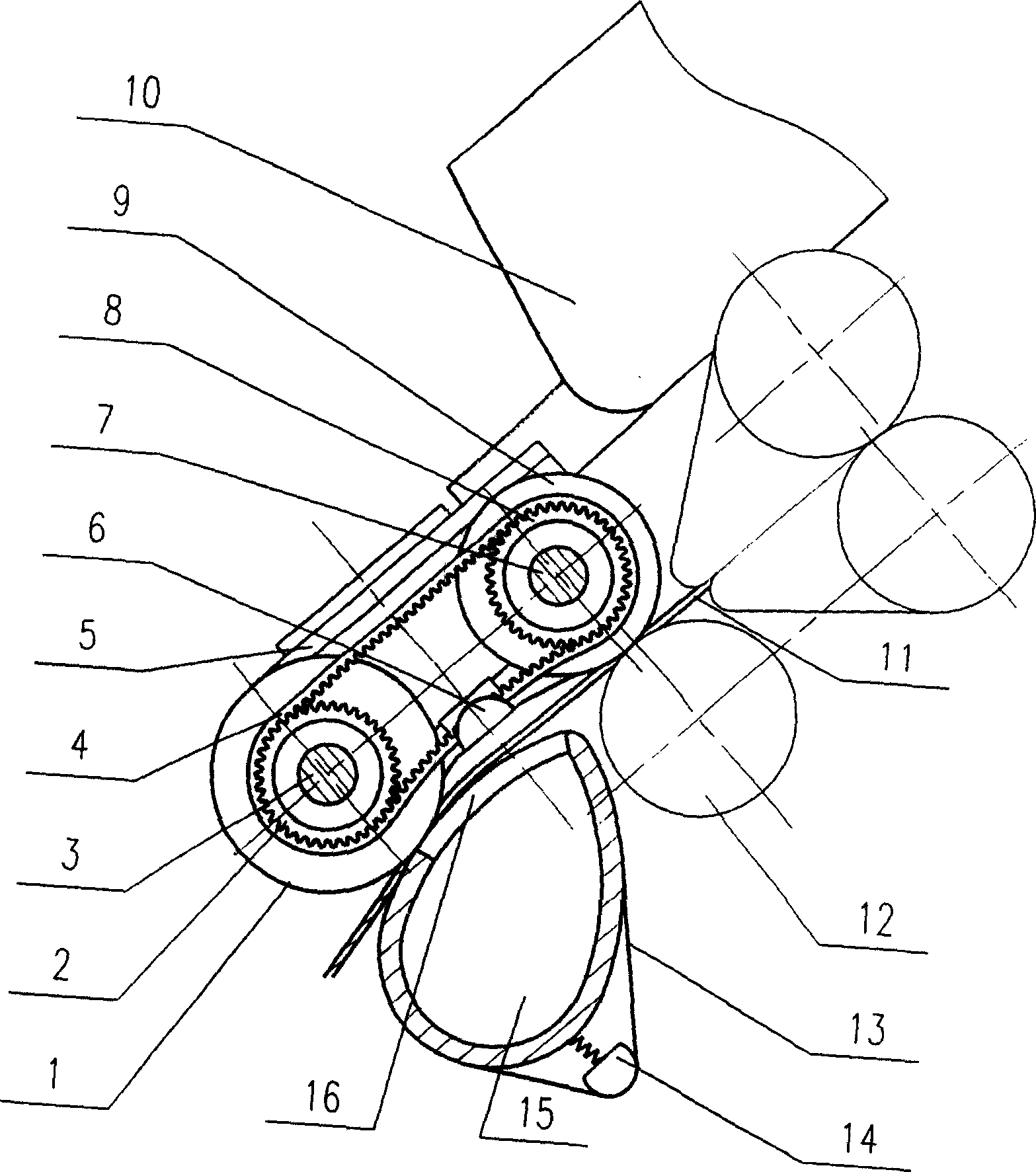
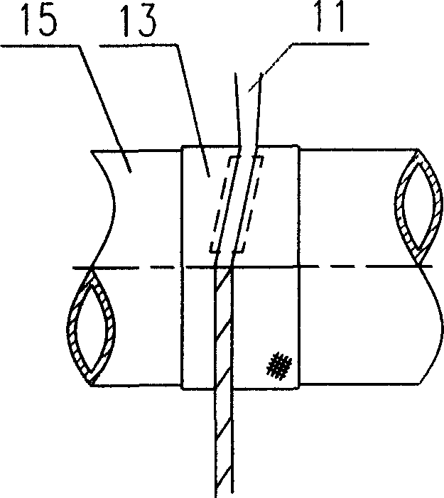
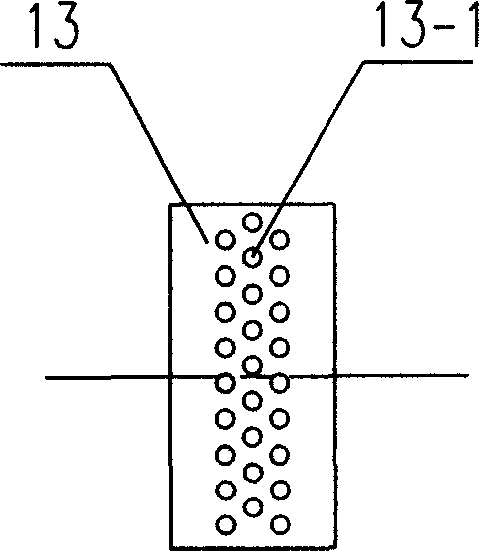
[0011] figure 1 In the compact ring spinning fiber gathering device shown, a front top roller shaft 7 and a gathering top roller shaft 3 are respectively installed on the bracket 5, and the front top roller shaft 7 and the gathering top roller shaft 3 are respectively rotatably installed with the front The top roller 9 and the gathering roller 1. The front roller 12 is located below the front top roller 9, and the front roller 12 and the front top roller 9 form a fiber bundle output nip; below the gathering top roller 1, a suction pipe 15 is arranged, and the suction pipe 15 is connected to the fiber bundle There is a suction groove 16 at the corresponding position of the path. The front top roller 9 and the gathering roller 1 are respectively fixedly connected with the front top roller synchronous belt wheel 8 and the gathering roller synchronous belt wheel 2, and the front top roller synchronous belt wheel 8 and the gathering synchronous roller The pulley 2 is driven by meshin...


PUM


Abstract

The invention provides a compact frame spinning fiber nesting device, which comprises a support, a front leather roller, a nesting leather roller, and an indraft tube arranged under the nesting leather roller. An indraft groove is arranged in the position of said indraft tube, which corresponds to the fiber path, the indraft tube has holed leather ring, and synchronous pulleys, which are driven in gear by serrated belt are fixedly connected with said front leather roller and said nesting leather roller. The invention effectively controls the fiber bundle in spinning course and eliminates twisting triangular space, as a result, produces yarn with less hairiness, has simple, compact structure, stable drive, better resultant yarn, and is convenient for maintenance and use.

Description

Technical field [0001] The invention relates to a ring spinning frame, in particular to the improvement of the fiber strand gathering device of the drafting system of the ring spinning frame. Background technique [0002] In the traditional spinning system, when the fiber bundle passes through the rear zone drafting and the front zone drafting of the ring spinning frame drafting system to reach the nip of the front roller, the fiber strands are output to the twisting point of the spun yarn. There is a spinning triangle without twisting. Since the fibers are basically out of control in this triangle, the fibers are easily separated and protrude from the area to become flying flowers and hairiness. In addition, the tension of the fibers in each part of the triangle is not consistent. It affects the strength index of spun yarn. Therefore, the existence of spinning triangle seriously restricts the improvement of yarn production rate and finished product quality. In order to eliminate...

Claims


Application Information

Patent Timeline
IPC IPC(8): D01H1/02D01H5/26D01H5/66
Inventor 朱鹏王平
Owner DONGTAI TEXTILE MASCH CO LTD
Learn More