
Light emitting unit structure with different colour on two faces

A technology of light-emitting unit and light-emitting element, which is applied in the direction of electroluminescence light source, light source, electric light source, etc., and can solve the problems of reducing light use efficiency and so on

Inactive Publication Date: 2004-12-08
WINTEK CORP
View PDF0 Cites 3 Cited by
  • Summary
  • Abstract
  • Description
  • Claims
  • Application Information

AI Technical Summary

Problems solved by technology

However, this method is not suitable for self-luminous flat-panel displays such as small molecule electroluminescent devices (Organic Light Emitting Diode; OLED) and polymer electroluminescent devices (Ploymer Light Emitting Diode; PLED). Water absorption will cause deterioration of light-emitting elements such as OLED and PLED, and photoresist will absorb part of the light and reduce the efficiency of light use

Method used


Image

  • Light emitting unit structure with different colour on two faces
  • Light emitting unit structure with different colour on two faces
  • Light emitting unit structure with different colour on two faces

Examples


Embodiment Construction

[0013] Relevant detailed description and technical contents of the present invention are as follows with regard to coordinating accompanying drawings now:

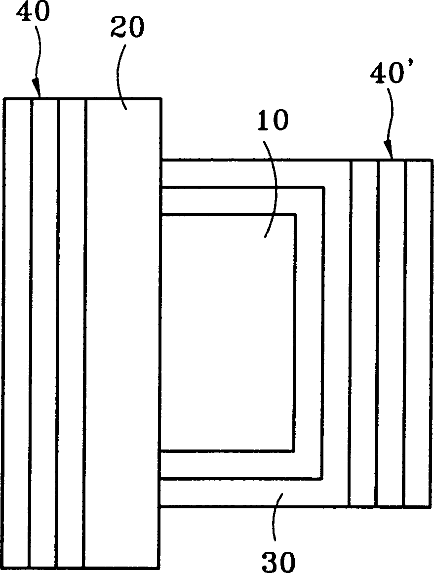
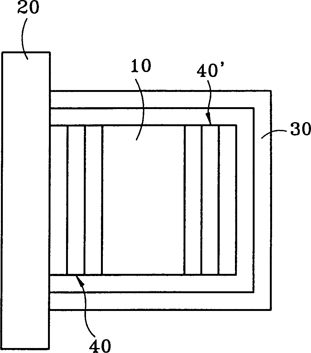
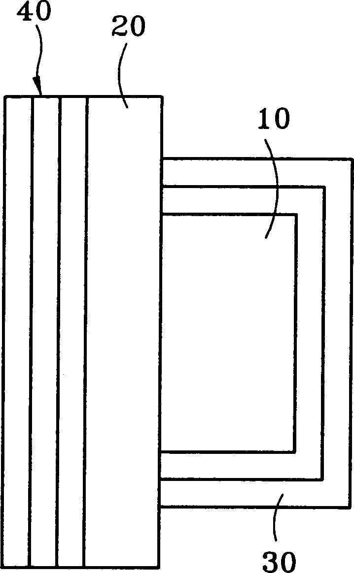
[0014] see figure 1 As shown, it is a schematic diagram of the first state of the light-emitting unit structure of the present invention. As shown in the figure: the present invention utilizes an optical inorganic thin film 40, 40' structure, and the optical inorganic thin film 40, 40' combines self-luminous transparent light-emitting The element 10 can realize the purpose of emitting light of different colors on both sides. The way of making is as follows, coating an optical inorganic thin film 40 on the outside of the transparent substrate 20, and coating an optical inorganic thin film 40' on the inside or outside of the transparent package cover to have high-pass filter (High pass filter), low-frequency filter (Low pass filter) or band pass filter (Band pass filter), using various optical inorganic thin films 40, 40' t...


PUM


Abstract

Thin film filter made form optical inorganic thin film is adopted in the invention. Character of not absorbing hydrosphere of filter made form optical inorganic thin film will not cause harmful effect on luminous element. More over, material of the optical thin film possesses character of not absorbing light so that light is filtered totally. Needed optical inorganic thin film is coated on electrodes on two sides of component or outside transparent base plate and transparent packaging cover. When light emitted from luminous element passes through color filter composed of optical inorganic thin films, which filter out color lights.

Description

technical field [0001] The invention relates to a structure of a light-emitting unit whose two sides emit light of different colors, in particular to a structure of a light-emitting element in a flat-panel display whose two sides emit light of different colors. Background technique [0002] The demand for Flat Panel Display (FPD) is becoming more and more urgent, and under the current global market trend towards thinner, smaller and power-saving, cathode ray tube (CRT) has been gradually replaced by FPD. The technologies currently used in FPD mainly include the following: plasma display (Plasma Display), liquid crystal display (Liquid Crystal Display), electroluminescent display (Electroluminescent Display), light emitting diode (Light Emitting Diode), vacuum fluorescent display (Vacuum Fluorescent Display), Field Emission Display (Field Emission Display) and Electrochromic Display (Electrochromic Display), etc. [0003] Organic Light Emitting Diodes (OLED) displays can be ...

Claims


Application Information

Patent Timeline
IPC IPC(8): G09F9/30H01L31/12H01L33/58H05B33/00
Inventor 黄颜明张俊钦刘怡萱
Owner WINTEK CORP
Learn More