
Driving system of mixed power vehicle

A hybrid electric vehicle and drive system technology, applied in the direction of electric vehicles, power devices, pneumatic power devices, etc., can solve the problem of no generator, etc., and achieve the effects of less device changes, easy logic control, and low emissions

Inactive Publication Date: 2004-12-08
同济大学汽车学院
View PDF0 Cites 23 Cited by
  • Summary
  • Abstract
  • Description
  • Claims
  • Application Information

AI Technical Summary

Problems solved by technology

The driving schemes of existing hybrid electric vehicles include series, parallel and hybrid. They have their own advantages and disadvantages in terms of control strategy, emission, use, vehicle layout, price and prime mover selection. Commonly driven, and the rear wheels are driven by hub motors, and the road is used as a medium to form a force-parallel four-wheel drive form

Method used


Image

  • Driving system of mixed power vehicle
  • Driving system of mixed power vehicle

Examples


Embodiment Construction

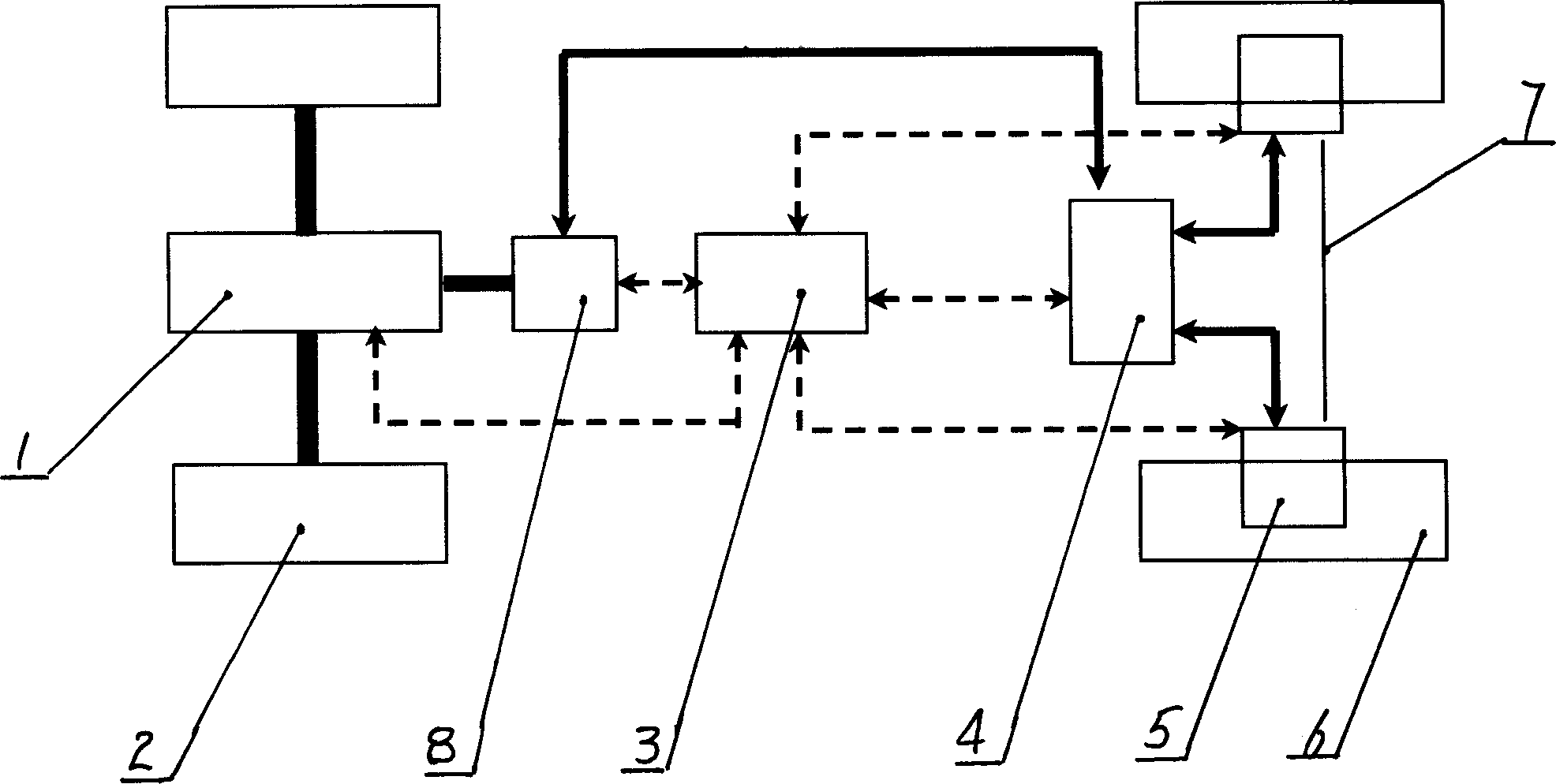
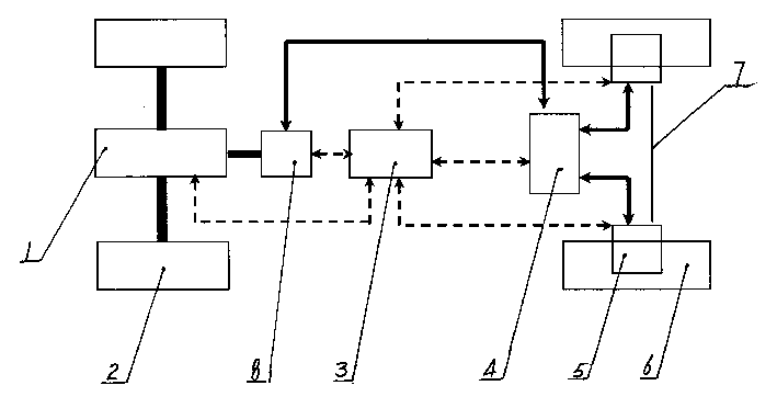
[0008] The present invention will be further described below in conjunction with accompanying drawing 1.

[0009] The present invention comprises an engine 1, a front wheel 2, a storage battery 4, an in-wheel motor 5, a generator 8, a rear wheel 6, and a rear axle 7, wherein a central control unit 3 and a generator 8 are arranged between the front wheel 2 and the rear wheel 6 And storage battery 4, engine 1 and generator 8 are connected in series, central control unit 3 is located between generator 8 and storage battery 4, storage battery 4 is in the middle front end of rear axle 7, and hub motor 5 is arranged in the hub of rear wheel 6, and hub The stator of the motor 5 is fixed on the rear axle 7, and its rotor is fixed to the hub of the rear wheel 6 and rotates with the wheel. The central control unit 3 is connected to the engine 1, the battery 4 and the hub motor 5 through sensors, and the generator 8 is connected to the hub motor 5 through sensors. It is connected with th...


PUM


Abstract

A drive system with mixed power for car is composed of enigne, front and back wheels, electric accumulator, wheel motors, electric generator, back bridge, and central control unit between front and back wheels. It features its two power sources used to drive the car. Its advantages are high P / C ratio and lower environmental pollution.

Description

technical field [0001] The present invention relates to an automobile drive system, more specifically, it relates to a hybrid electric automobile drive system driven by two power sources. Background technique [0002] With the improvement of people's living standards, cars are used more and more widely, and people's requirements for cars are getting higher and higher, and the development of cars is developing in the direction of comfort and intelligence. The driving form of traditional cars is driven by internal combustion engines. In recent years, electric vehicles and hybrid vehicles have developed rapidly. Hybrid vehicles combine electric motors and auxiliary power units in one vehicle as driving force. The auxiliary power unit is actually a small Fuel engine or power generator set. The driving schemes of existing hybrid electric vehicles include series, parallel and hybrid. They have their own advantages and disadvantages in terms of control strategy, emission, use, veh...

Claims


Application Information

Patent Timeline
IPC IPC(8): B60K6/22B60L11/00B60L11/18B60T1/10
CPCY02T10/648Y02T10/646Y02T10/7005Y02T10/64Y02T10/70
Inventor 余卓平杜爱民陈礼璠沈勇陈辛波
Owner 同济大学汽车学院
Learn More