Non-evaporation type getter, display unit and production method for them

A non-evaporative, getter technology, applied in the manufacture of chemical instruments and methods, image/graphic display tubes, ships or lead-in wires, etc., can solve problems such as difficult to set non-evaporative getters, and achieve shrinkage stable effect

Inactive Publication Date: 2004-12-01
SONY GRP CORP
View PDF1 Cites 3 Cited by
  • Summary
  • Abstract
  • Description
  • Claims
  • Application Information

AI Technical Summary

Problems solved by technology

[0011] This makes it difficult to set up non-evaporable getters, especially in flat panel display devices

Method used


Image

  • Non-evaporation type getter, display unit and production method for them
  • Non-evaporation type getter, display unit and production method for them
  • Non-evaporation type getter, display unit and production method for them

Examples


Embodiment Construction

[0063] The invention will now be described on the basis of an embodiment shown in the drawings.

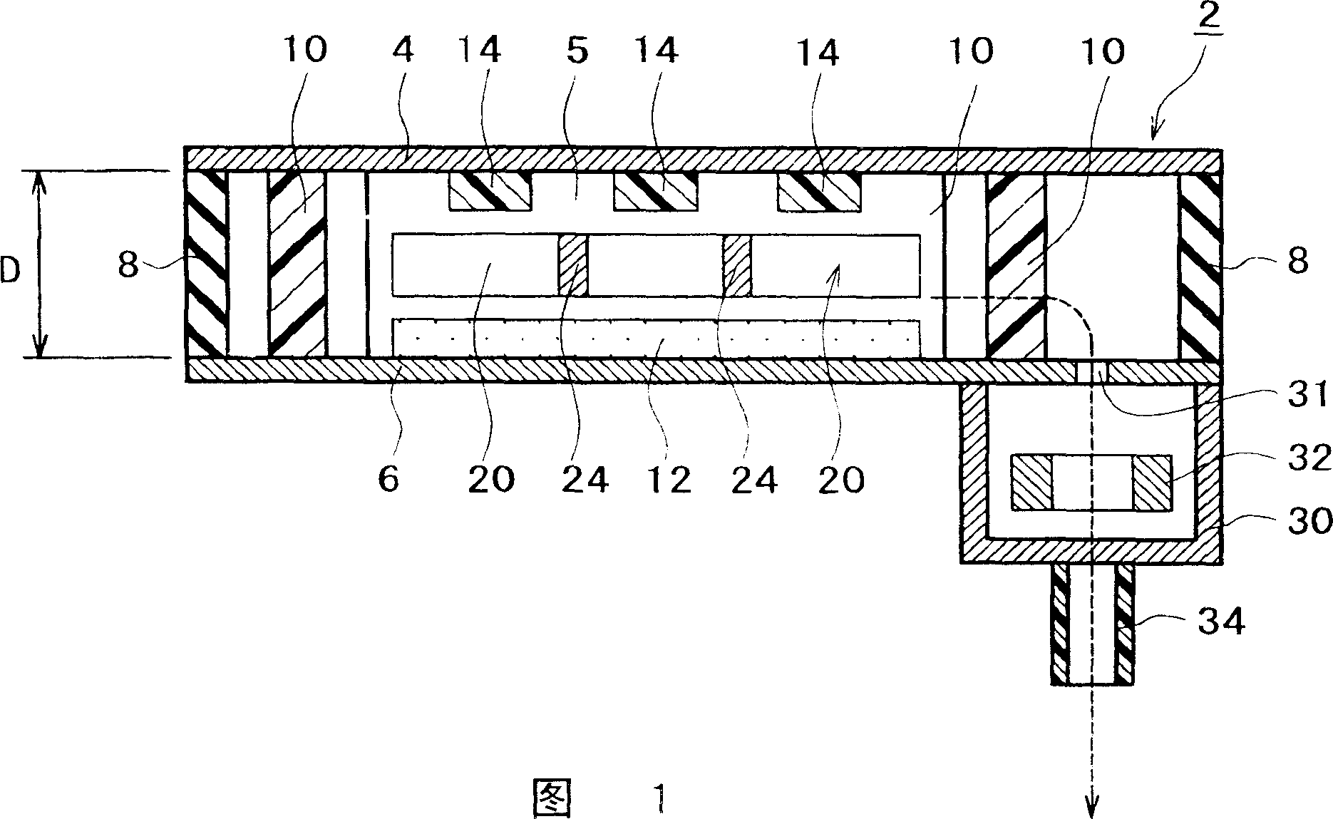
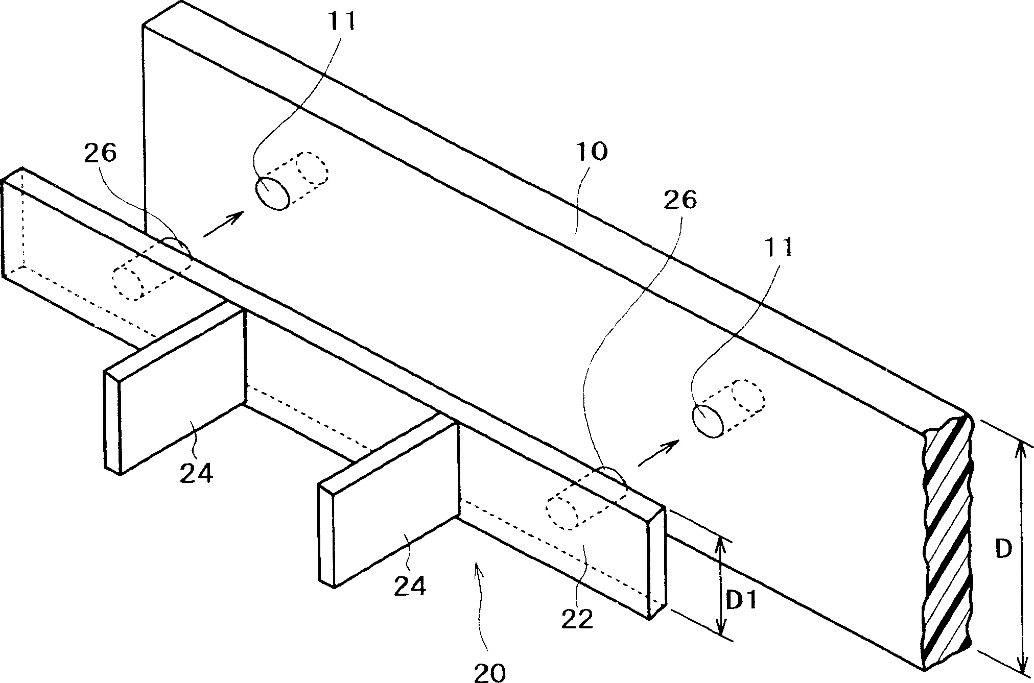
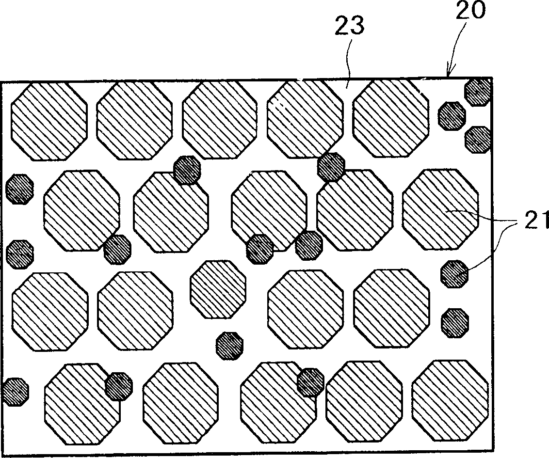
[0064] 1 is a general cross-sectional view of a flat panel display device according to an embodiment of the present invention; figure 2 is a perspective view showing the relationship between the separator and the non-evaporable getter shown in FIG. 1; Figure 3A is an enlarged conceptual diagram of a main part of a non-evaporable getter according to an embodiment of the present invention, Figure 3B is an enlarged conceptual diagram of a non-evaporable getter according to another embodiment of the present invention; Figure 4A to Figure 4D is a perspective view showing the shape of a non-evaporable getter according to another embodiment of the present invention; Figure 5A is a graph showing the gettering capacity of the non-evaporable getter according to one embodiment of the present invention and the gettering capacity of the conventional non-evaporable getter, Figure 5B is ...


PUM


Abstract

Disclosed are a non-evaporation type getter excellent in gettering effect, capable of maintaining the inside of a gas-tight container in a display apparatus, particularly a flat panel display apparatus or the like, in a high vacuum condition, easy to mount and less liable to contaminate the inside of the gas-tight container, a display apparatus including the getter, and methods of manufacturing the same. The non-evaporation type getter (20) includes a molded body including at least one element selected from the group consisting of Ti, Zr, Al, V, and Fe as a principal constituent thereof, the molded body formed by powder injection molding. The molded body is composed of a porous body having a porosity of 10 to 30%.

Description

technical field [0001] The present invention relates to a non-evaporable getter, a display device and a manufacturing method thereof. Background technique [0002] Flat panel display devices such as field emission displays (hereinafter abbreviated as FEDs) have been proposed in recent years, in which phosphors are irradiated with electron beams emitted from electron emission sources such as field emission devices to cause fluorescence The body emits light to form an image. [0003] In the FED, a substrate provided with electron emission sources arranged in a matrix form and a substrate provided with phosphors are disposed opposite to each other with a slight gap therebetween, and the peripheries of these substrates are sealed to form an airtight container, the inside of which is A high vacuum or an ultra-high vacuum is maintained, and the phosphor is irradiated with an electron beam emitted from an electron emission source to cause the phosphor to emit light, thereby displa...

Claims


Application Information

Patent Timeline
Patent Type & Authority Applications(China)
IPC IPC(8): B22F3/02B01J20/02B22F3/11B22F3/22B22F3/24H01J7/18H01J9/24H01J9/39H01J29/87H01J29/94H01J31/12
CPCB01J20/0229B01J20/0214B22F3/225B22F3/11H01J29/94B22F2998/00B01J20/0248B01J20/0211H01J7/183B01J20/02H01J7/18B01J20/3007B01J20/3204B01J20/3236
Inventor 长谷川阳二
Owner SONY GRP CORP
Why Eureka
Try Eureka