Eureka AIR delivers breakthrough ideas for toughest innovation challenges, trusted by R&D personnel around the world.

Dust collector for drill

a dust collector and drill bit technology, applied in the direction of thread cutting feeding device, metal-working machine components, manufacturing tools, etc., can solve the problems of drywall not only troublesome, but also potentially damaging to valuables around the area, so as to prevent the distribution of dust and debris

Active Publication Date: 2008-07-08
KESTEN DOUGLAS
View PDF18 Cites 27 Cited by
  • Summary
  • Abstract
  • Description
  • Claims
  • Application Information

AI Technical Summary

Benefits of technology

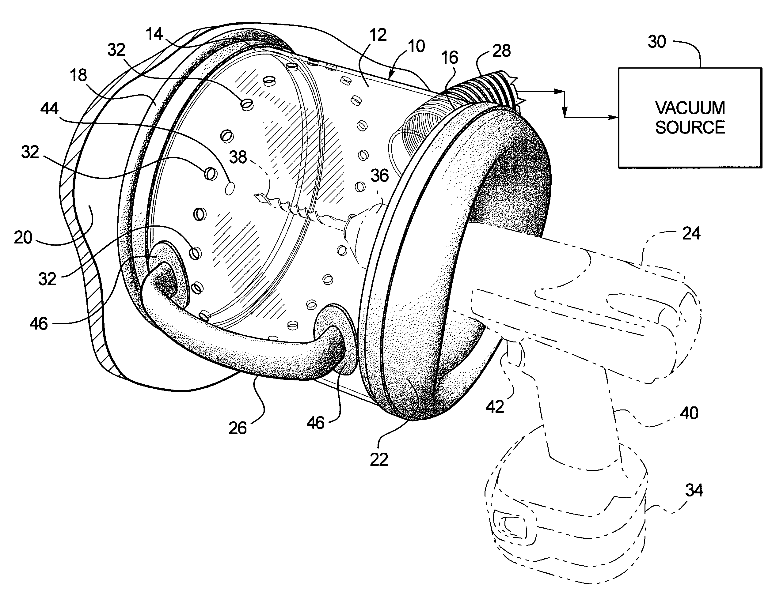
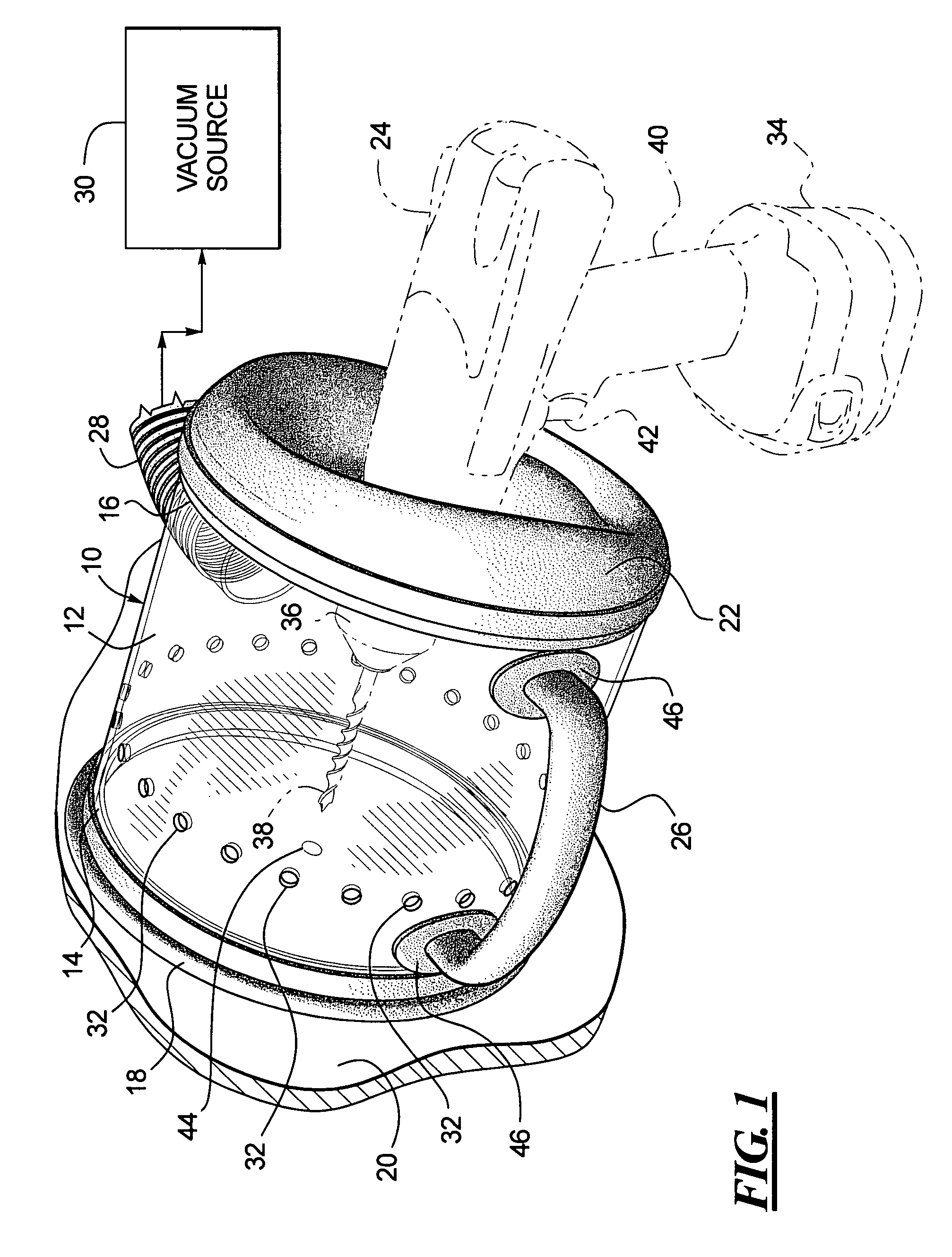
[0006]The present invention provides an apparatus for preventing the distribution of dust and debris during drilling. In particular, an apparatus is provided that fits onto a standard power drill or other power tool as used by persons performing maintenance or installation work in a dwelling or other interior space and which uses a standard vacuum source, the device being constructed to press against the surface being drilled and to collect substantially all dust and debris created during the drilling operation.

Problems solved by technology

Use of a power drill in which is mounted a high-speed drill bit results in the generation of debris and dust as a hole is drilled into a surface.
The dust from drilling into drywall is not only troublesome to clean up following maintenance work or installation of new lights, for example, but is also potentially damaging to valuables around the area of the drilling.
The resulting dust from the drilling can adhere to the unprotected surfaces of the valuables, thereby necessitating removing or covering the valuables.
It possible that the dust and debris of drilling and working some materials may be harmful should the dust be carried into the air.
The dust from some plasters and drywall can harm paintings, for example.
Others can be harmful when inhaled.

Method used


Image

  • Dust collector for drill
  • Dust collector for drill
  • Dust collector for drill

Examples


Embodiment Construction

[0013]The present invention provides a dust collector for use with power tools, such as power drills or other power equipment. It is envisioned that the present apparatus may be used with a variety of power hand tools, including saws such as reciprocating saws, high speed rotary tools such as made by Dremel and others, sanders, sandblasting and etching tools, and the like.

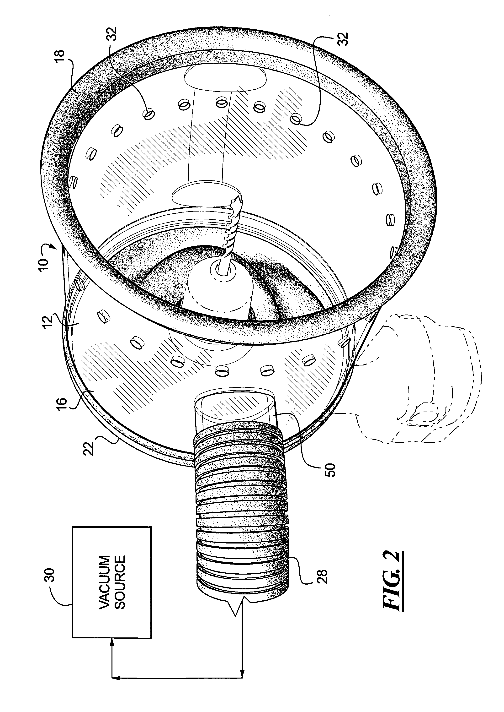
[0014]With reference first to FIG. 1, a dust collecting apparatus 10 includes a cylinder 12 having a first end 14 and a second end 16. The first end 14 of the cylinder 12 include a gasket 18 that presses against a wall, ceiling, or other surface 20. The second end 16 has a flexible web or boot 22. The web 22 fits onto a power drill 24, which is shown in phantom. A handle 26 is provided on the side of the cylinder 12 so that the device can be pressed against the wall or ceiling 20. A hose 28 is connected to the cylinder 12, the hose 28 being connected at its opposite end to a vacuum source 30. An arrangement of hole...


PUM

PropertyMeasurementUnit
lengthaaaaaaaaaa
diameteraaaaaaaaaa
diameteraaaaaaaaaa

Abstract

A dust collector for a power drill is provided that includes a cylinder of sufficient size to accept at least a foremost portion of a power drill. The cylinder includes a gasket or seal at the forward end for contact with the wall or working surface to be drilled. A rubber or other elastic membrane or web is provided over the opposite end of the cylinder and an opening is formed in the membrane or web to fit snugly around the forward end of a power drill. A narrowing or neck may be used in place of the web to provide an opening for the forward end of a power drill. An arrangement of holes is formed in the wall of the cylinder. A vacuum hose is connected to the cylinder by a direct connection to the cylinder or by connection of the vacuum hose to a pistol grip handle attached to the cylinder. By connecting the vacuum hose to a shop vacuum, household vacuum or other vacuum source, the power drill may be inserted into the opening in the web and holes drilled in walls or other surfaces without disbursing dust into the surrounding area.

Description

BACKGROUND OF THE INVENTION[0001]1. Field of the Invention[0002]The present invention relates generally to a dust-collecting apparatus for use with a drill and in particular to a vacuum-operated dust collector adapted to fit onto a power drill.[0003]2. Description of the Related Art[0004]Use of a power drill in which is mounted a high-speed drill bit results in the generation of debris and dust as a hole is drilled into a surface. For some materials such as wood the debris is easily collected near the drilling site after drilling is completed. However, for other materials such as gypsum board, or as it is commonly referred to, drywall, fine dust particles spread through the air and accumulate on services over a widespread area. The dust from drilling into drywall is not only troublesome to clean up following maintenance work or installation of new lights, for example, but is also potentially damaging to valuables around the area of the drilling. For example, it is common that art co...

Claims


Application Information

Patent Timeline
Patent Type & Authority Patents(United States)
IPC IPC(8): B23B47/34
CPCB23Q11/0046Y10T408/50
Inventor KESTEN, DOUGLAS
Owner KESTEN DOUGLAS
Why Eureka
Eureka Blog
Learn More