
Backlight module and liquid crystal display device

A liquid crystal display and backlight module technology, which is applied to instruments, optics, nonlinear optics, etc., can solve the problems of enlarged size, warping deformation, and inability to support the lamp tube 106, and achieve the effect of avoiding warping deformation and avoiding deformation.

Inactive Publication Date: 2004-11-24
AU OPTRONICS CORP
View PDF0 Cites 12 Cited by
  • Summary
  • Abstract
  • Description
  • Claims
  • Application Information

AI Technical Summary

Problems solved by technology

[0007] If used as figure 1 Although the shown backlight module 100 can support the diffuser plate 108 to avoid warping and deformation of the diffuser plate 108, however, this structure cannot support the lamp tube 106. When the size of the liquid crystal display panel is larger, the lamp tube The size of 106 will also increase accordingly, so that the lamp tube 106 is easily warped and deformed due to insufficient rigidity, thereby affecting the optical characteristics of the backlight module 100
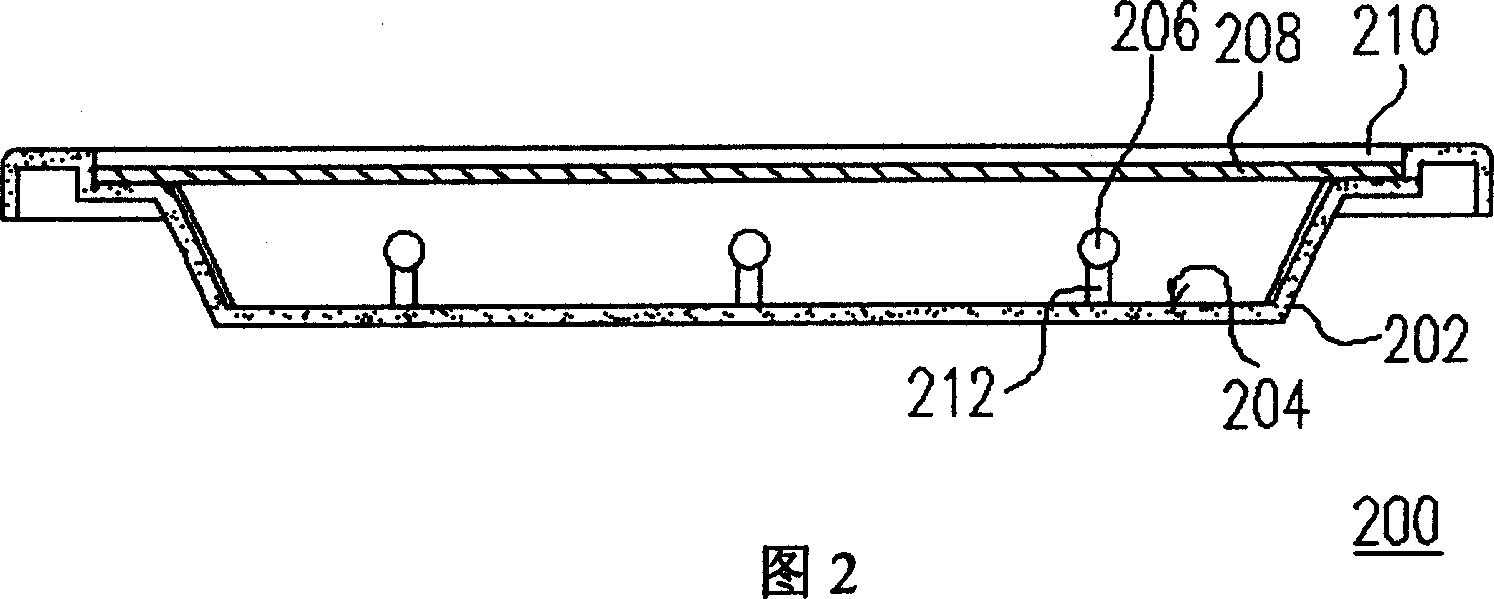
[0008] On the other hand, if the backlight module 200 shown in FIG. 2 is used, although the lamp tube 206 can be supported to avoid warping and deformation of the lamp tube 206, this structure cannot support the diffuser plate 208. When the liquid crystal When the size of the display panel is larger, the size of the diffuser 208 will also be larger, so that the diffuser 208 is prone to warping and deformation due to insufficient rigidity or thermal expansion, which will also affect the optical characteristics of the backlight module 200

Method used


Image

  • Backlight module and liquid crystal display device
  • Backlight module and liquid crystal display device
  • Backlight module and liquid crystal display device

Examples


Embodiment Construction

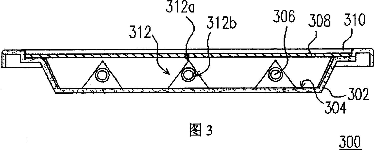
[0045] What Fig. 3 represented is the cross-sectional schematic view of the preferred embodiment of the backlight module of the present invention, and Figure 4 What is shown is a schematic cross-sectional view of the preferred embodiment of the backlight module of the present invention, the cross-section of which is perpendicular to that of FIG. 3 , and the backlight module 300 is a direct-type backlight module.

[0046] First, please refer to Figure 3 and Figure 4 The backlight module 300 of the present invention is mainly composed of a frame 302 , a reflector 304 , at least one lamp tube 306 , a diffuser plate 308 , a plurality of optical films 310 and at least one support member 312 .

[0047] The reflection sheet 304 is disposed on the bottom surface of the frame 302 , wherein the reflection sheet 304 is used to reflect the light emitted by the lamp tube 306 not toward the display panel (not shown), so as to improve the utilization efficiency of the lamp tube 306 .

[004...


PUM


Abstract

The back light module consists of one frame, one reflecting sheet, at least one lamp tube, one diffusion board, several optical diaphragms and at least one support member. The reflecting sheet is configured in the bottom of the frame, the lamp tube is configured inside the frame and over the reflecting sheet, the diffusion board is configured on the frame and located over the lamp tube, the optical diaphragms are configured on the diffusion board, and the support member on the reflecting sheet includes two support parts to support the diffusion board and the lamp tube separately.

Description

technical field [0001] The present invention relates to a backlight module (Back Light Module) and a liquid crystal display (Liquid Crystal Display, LCD), and in particular to a backlight module and a backlight module capable of simultaneously supporting a diffuser plate and a lamp tube to avoid deformation of both. LCD Monitor. Background technique [0002] In order to adapt to the modern lifestyle, the volume of video or image devices is becoming thinner and thinner. Although the traditional cathode ray display (CRT) still has its advantages, due to the structure of the internal electronic cavity, the display is bulky and takes up space, and there are still problems such as radiation damage to the eyes when displaying. Therefore, flat panel displays developed in conjunction with optoelectronic technology and semiconductor manufacturing technology, such as liquid crystal displays (LCDs), organic light emitting displays (OLEDs) or plasma displays (Plasma Display Panels, PDP...

Claims


Application Information

Patent Timeline
Patent Type & Authority Applications(China)
IPC IPC(8): G02F1/13357
Inventor 郭建宏游川倍柳汉洲
Owner AU OPTRONICS CORP
Learn More