
Static microactuator with electric insulative movable portion and related driving circuit

A technology of actuators and electrical insulating materials, applied in the directions of electrostatic generators/motors, generators/motors, driving/moving recording heads, etc., which can solve the problems of increasing noise by magnetic signals

Inactive Publication Date: 2004-10-06
HITACHI GLOBAL STORAGE TECH NETHERLANDS BV
View PDF3 Cites 3 Cited by
  • Summary
  • Abstract
  • Description
  • Claims
  • Application Information

AI Technical Summary

Problems solved by technology

Also, because the slider ground is connected to the microactuator ground, there is an electrical connection between the microactuator driver signal and the magnetic signal from the read / write head, which adds significant hope for noise

Method used


Image

  • Static microactuator with electric insulative movable portion and related driving circuit
  • Static microactuator with electric insulative movable portion and related driving circuit
  • Static microactuator with electric insulative movable portion and related driving circuit

Examples


Embodiment approach

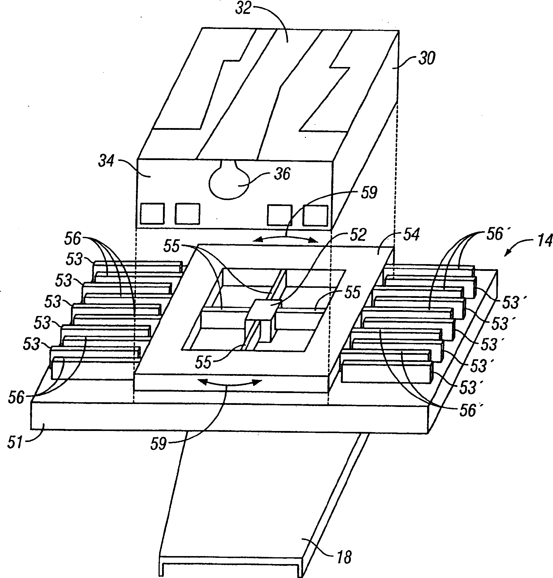
[0025]FIG. 6 shows the microactuator 114 and its driving circuit of the present invention. Microactuator 114 has a movable frame 140 that includes a generally rectangular interior 141 and exterior 142 formed from a conductive metal, typically nickel. The two frame parts 141 and 142 are connected together but are electrically isolated from each other by an electrically insulating material 143 . The frame 140 has two opposing side walls 145, 147, each of which faces a respective set of fixed electrode branches 153, 153' spaced apart on the substrate 151 . The outer portion 142 of the frame 140 also has side walls 161, 163 which support respective sets of movable electrode branches 156, 156'. Walls 161 , 145 , and walls 163 , 147 are connected by insulating material 143 . Figure 7 is a partial view of FIG. 6 (without the optional bonding platform connected to the interior 141 of the frame 140), which more clearly shows how the slider is electrically isolated from the movable el...


PUM


Abstract

A bidirectional electrostatic rotary microactuator has two sets of fixed electrodes, one set for driving the microactuator counterclockwise and the other set for driving it clockwise, and a rotatable frame that has movable electrodes attached to its outer wall and interleaved between the fixed electrodes. A layer of insulating material is located between the outer wall to which the movable electrodes are attached and the remainder of the frame so that the movable electrodes are electrically isolated. The frame is maintained at ground electrical potential and the movable electrodes at a fixed non-zero electrical potential. The microactuator is driven by applying a plus or minus voltage to one set of fixed electrodes and the opposite voltage to the other set, while maintaining the movable electrodes at a fixed non-zero voltage. The microactuator is usable as a secondary actuator in a disk drive for fine positioning the read / write head.

Description

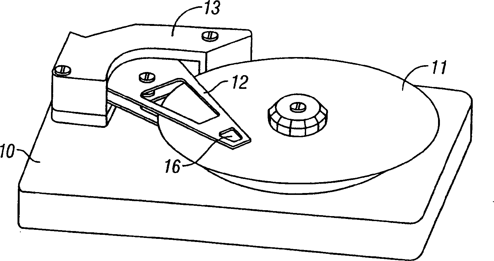
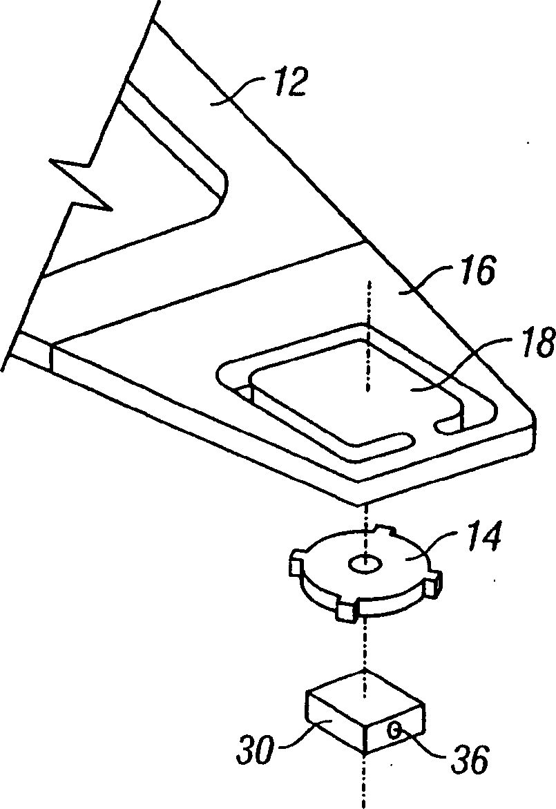
technical field [0001] This invention relates generally to electrostatic microactuators, and more particularly to electrostatic microactuators as auxiliary read / write actuators in magnetic recording disk drives. Background technique [0002] Data recording disk drives, such as magnetic recording drives, store information in data tracks located on the data surface of a rotatable magnetic recording disk. The read / write head or sensor that reads data from and writes data to the data surface is located on an air bearing slider that is supported by an air bearing on a rotating disk. The slider is attached to a flexible cantilever at the end of the rigid arm. Disk drive actuators are typically rotary voice coil motors (VCMs), which typically move the actuator arm and attached suspension and slider radially to position the head in the position used to receive pre-recorded servo position information from the data surface. Under the control of the servo control system, it is positi...

Claims


Application Information

Patent Timeline
Patent Type & Authority Applications(China)
IPC IPC(8): G11B5/596G11B5/55G11B21/08G11B21/10G11B21/21H02N1/00
CPCG11B5/5552G11B21/08
Inventor 敏树平野杨宏渊
Owner HITACHI GLOBAL STORAGE TECH NETHERLANDS BV
Learn More