
Exhaust gas quide structure of closed compressor

A guide structure and compressor technology, applied in mechanical equipment, machines/engines, rotary piston machinery, etc., can solve problems such as increasing the input power and eccentric torque of the electric mechanism, hindering the discharge of compressed gas, and extending the rotating shaft. Achieve the effects of reducing vibration and noise, reducing production costs, and reducing input power

Inactive Publication Date: 2004-09-29
LG ELECTRONICS (TIANJIN) APPLIANCES CO LTD
View PDF0 Cites 6 Cited by
  • Summary
  • Abstract
  • Description
  • Claims
  • Application Information

AI Technical Summary

Problems solved by technology

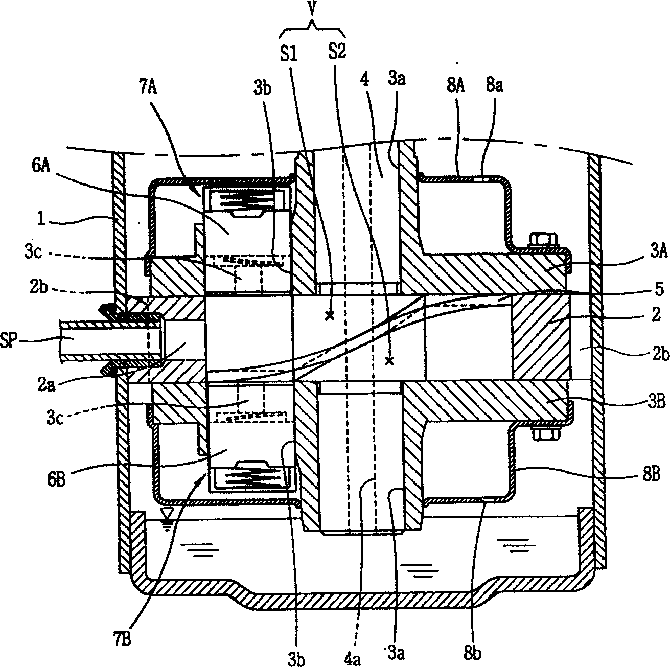
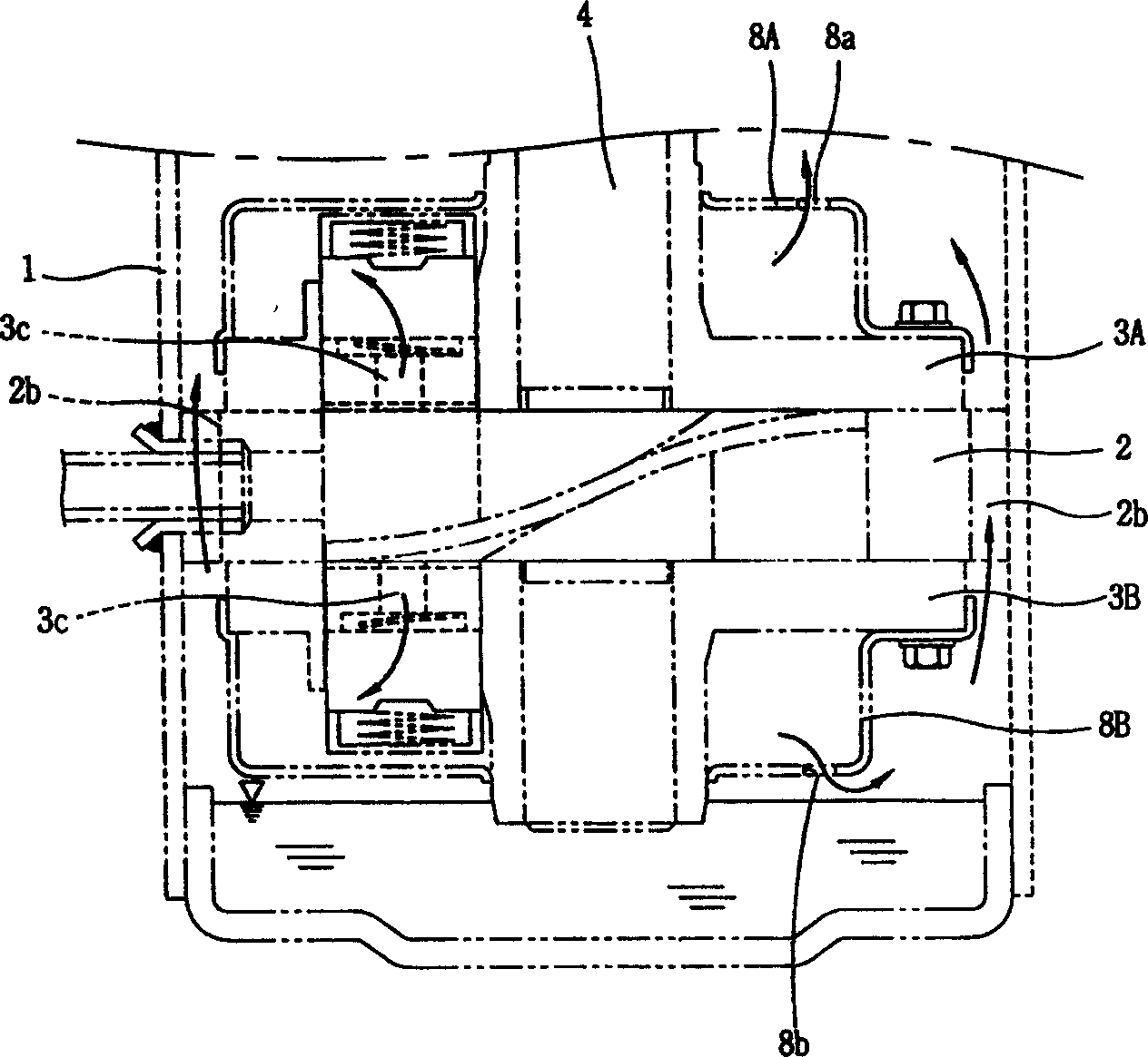
[0013] The above-mentioned existing hermetic compressor has the following disadvantages: in order to cool the motor mechanism of the compressor and lubricate the sliding parts of the compression mechanism, a certain amount of oil needs to be loaded into the inner cavity of the casing 1 in advance. If the oil level is higher than that of the lower muffler The position of the exhaust hole 8b of 8B, otherwise, when the compressor starts, the oil stored at the bottom of the inner cavity of the casing 1 will flow into the lower muffler 8B through the exhaust hole 8b of the lower muffler 8B, which may hinder the compression Gas discharge, so the oil level should be lower than the exhaust hole 8b of the lower muffler 8B
But prolonging the length of the rotating shaft 4 will not only increase the input power and eccentric torque of the electric mechanism, increase the production cost, but also increase the volume of the compressor, thereby reducing the space utilization efficiency

Method used


Image

  • Exhaust gas quide structure of closed compressor
  • Exhaust gas quide structure of closed compressor
  • Exhaust gas quide structure of closed compressor

Examples


Embodiment Construction

[0038] Below in conjunction with accompanying drawing and specific embodiment the present invention is described in further detail:

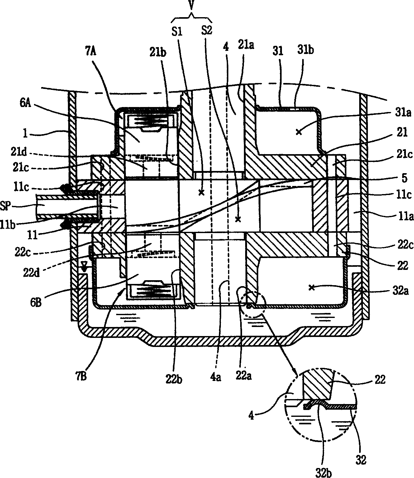
[0039] Such as image 3 and Figure 4 As shown, the hermetic compressor applicable to the exhaust guide structure of the hermetic compressor of the present invention includes: a casing 1, a cylinder 11, a partition plate 5, a rotating shaft 4, a first guide plate 6A, a second guide plate 6B, and an upper bearing Plate 21, lower bearing plate 22, upper muffler 31 and lower muffler 32; a certain amount of oil is installed at the bottom of the cavity of the shell 1; the cylinder 11 is fixedly installed on the upper half of the cavity of the shell 1, On the side wall of the cylinder 11, an air intake 11b connected with the internal space V of the cylinder 11 is formed; the rotating shaft 4 is connected with the rotor (not shown) of the electric mechanism; the division plate 5 connects the cylinder The internal space V of 11 is divided into a first...


PUM


Abstract

The present invention discloses a kind of gas exhaust guiding structure of closed compressor, and features that the lower bearing board has at least one formed first gas flow path, the upper board has at least one formed third gas flow path, and the cylinder wall in the engine recovering flow path side has at least one formed second gas flow path communicated with the first gas flow path and the third gas flow path, so that the compressed gas from the lower silencer may be exhausted to the inner cavity of compressor casing through the first gas flow path, the second gas flow path and the third gas flow path successively. The advantages of the present invention include reduced length of rotating compressor shaft, reduced input power, lowered manufacture cost and decreased vibration noise of compressor.

Description

technical field [0001] The invention relates to a hermetic compressor, in particular to an exhaust guide structure of a hermetic compressor. Background technique [0002] Existing high-pressure hermetic compressors generally consist of a motor mechanism and a compression mechanism. The electric mechanism is generally an electric motor composed of a stator and a rotor, which is arranged on the upper part of the inner cavity of the compressor shell and used to generate power for the compressor; the compression mechanism is arranged on the lower part of the electric mechanism to suck and compress and exhaust gas. [0003] Existing high-pressure hermetic compressors generally adopt a guide plate type exhaust guide structure. The guide plate type exhaust guide structure is to press the guide plate on the rotating body to divide the inner cavity of the cylinder into a suction area and a compression area. When the compressor is working, the rotary body rotates, and under the guid...

Claims


Application Information

Patent Timeline
IPC IPC(8): F04C18/356
Inventor 李长祐金永宗安炳河
Owner LG ELECTRONICS (TIANJIN) APPLIANCES CO LTD
Learn More