
Network reconfiguration, nodes and connecting object changing method

A technology for connecting objects and nodes. It is applied in the field of communication networks and can solve problems such as inability to properly build networks, complex network structures, and reduced communication speeds.

Active Publication Date: 2004-09-22
III 控股10有限责任公司
View PDF2 Cites 8 Cited by
  • Summary
  • Abstract
  • Description
  • Claims
  • Application Information

AI Technical Summary

Problems solved by technology

[0013] However, in the communication method described in the above-mentioned Japanese Unexamined Patent Publication No. 2002-111689, it can only cope with the case where the host is disconnected.
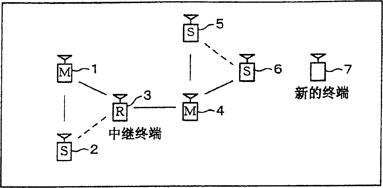
In addition, for example, in an environment where multiple networks with a one-to-many connection method are connected to each other, it is impossible to select an appropriate backup host, and it is impossible to properly construct the network
Therefore, there are problems that the network structure becomes complicated, the power consumption of the entire network increases due to the presence of too many master terminals in the network, and the retransmission processing increases due to the easy occurrence of packet collisions, resulting in a decrease in communication speed. drop etc.

Method used


Image

  • Network reconfiguration, nodes and connecting object changing method
  • Network reconfiguration, nodes and connecting object changing method
  • Network reconfiguration, nodes and connecting object changing method

Examples


no. 1 approach

[0052] An embodiment of the present invention will be described below with reference to FIGS. 2 to 10 . FIG. 2 shows the internal configuration of the terminal 10 constituting the network of this embodiment. As shown in the figure, the terminal 10 has the following parts: a communication unit (communication unit) 11, which communicates with other terminals 10; a detection unit (detection unit) 12, which detects a communicable terminal; a storage unit (storage unit) 13 , storing the detection information obtained from the communication unit 11 and the detection unit 12; the control unit (master terminal selection unit, construction unit) 14, controlling each part; and the notification unit (notification unit) 15, to notify the outside.

[0053] FIG. 3 shows changes in the working state of the terminal 10 shown in FIG. 2 . As shown in FIG. 3 , the working state of the terminal 10 is one of an idle state (a), a detection information receiving state (b), a cyclic detection state ...

no. 2 approach

[0087] Another embodiment of the present invention will be described below with reference to FIGS. 11 to 17 . FIG. 11 shows the configuration of a communication device based on the communication method of the present invention. This communication device includes a network control module 20 and a flag storage module 26 .

[0088] Network control module 20 is made up of following parts: control processing part (main terminal selection unit, construction unit) 21, control system; Detection processing part (detection unit) 22, detects the communication terminal that can communicate; Storage processing part (storage unit) 23 , to store detection information; a communication processing unit (communication unit) 24, to communicate with other communication terminals; and a notification processing unit (notification unit) 25, to notify the outside. Each of the processing units 21 to 25 can perform parallel processing. In addition, in order to cooperate with the processing units 21-25...


PUM


Abstract

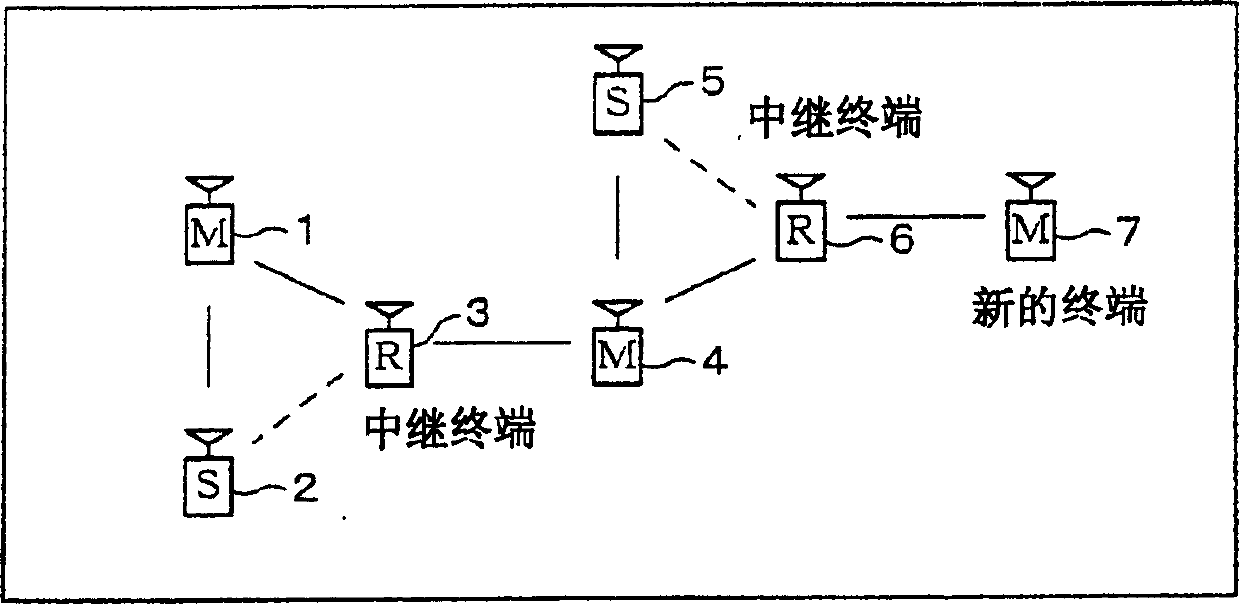
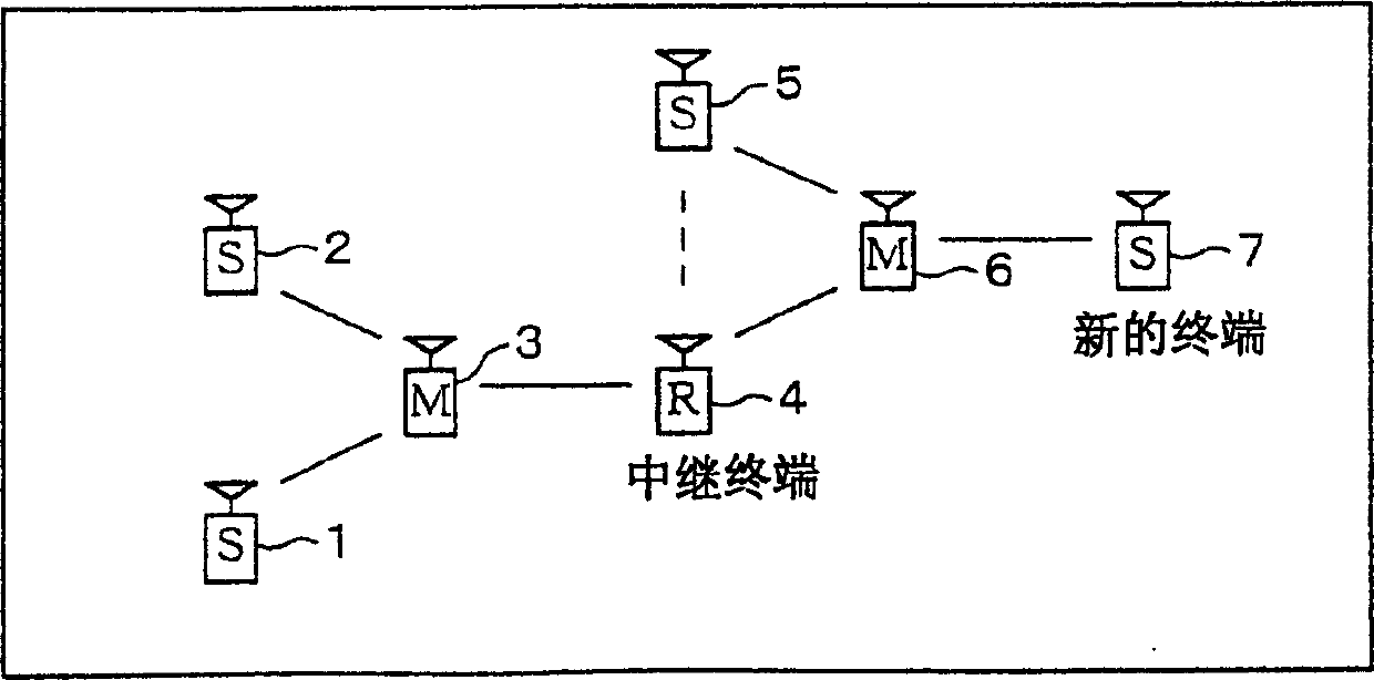
A method of reconfiguring a network including a plurality of sub-networks in which at least one slave terminal is wireless-linked with a master terminal is disclosed. Firstly, each terminal detects a wireless-linkable node. Secondly, detection information including the results of the detections in the terminals is generated. Thirdly, with reference to the generated detection information, a master terminal is selected in such a manner as to minimize the total number of the master terminals. Finally, a sub-network including the selected master terminal is constructed.

Description

technical field [0001] The present invention relates to a communication network, and more particularly to a network reconfiguration method, a node, a connection object changing method, a network reconfiguration program, A target change program and a recording medium recording the program are linked. Background technique [0002] So far, in the case of mutual communication between devices (hereinafter referred to as "terminals") having a communication function such as personal mobile information terminals (Personal Digital Assistant, hereinafter referred to as PDA), notebook computers, mobile phones, etc., Wired communication via cables such as RS-232C and USB (Universal Serial Bus) is the mainstream. [0003] On the other hand, recently, a short-distance wireless communication technology for performing wireless communication between terminals has been proposed. Representative short-range wireless communication technologies include IEEE802.11, IEEE802.15, and Bluetooth (reg...

Claims


Application Information

Patent Timeline
Patent Type & Authority Applications(China)
IPC IPC(8): H04L12/28H04B7/26H04L12/24H04W84/20
CPCH04L41/083H04W84/20H04L41/0833H04L41/0803H04L41/0856
Inventor 末次纯二
Owner III 控股10有限责任公司
Learn More