
Multiple-interleaved integrated circuit transformer

An integrated circuit and transformer technology, applied in the design field of interleaved transformer devices, can solve the problems of increasing the area occupied by the transformer, increasing the coil resistance and inductance, etc.

Inactive Publication Date: 2004-08-18
KONINKLIJKE PHILIPS ELECTRONICS NV
View PDF1 Cites 33 Cited by
  • Summary
  • Abstract
  • Description
  • Claims
  • Application Information

AI Technical Summary

Problems solved by technology

However, increasing the number of realized turns increases the resistance as well as the inductance of each coil
In coplanar transformers, increasing the number of actual turns significantly increases the area occupied by the transformer

Method used


Image

  • Multiple-interleaved integrated circuit transformer
  • Multiple-interleaved integrated circuit transformer
  • Multiple-interleaved integrated circuit transformer

Examples


Embodiment Construction

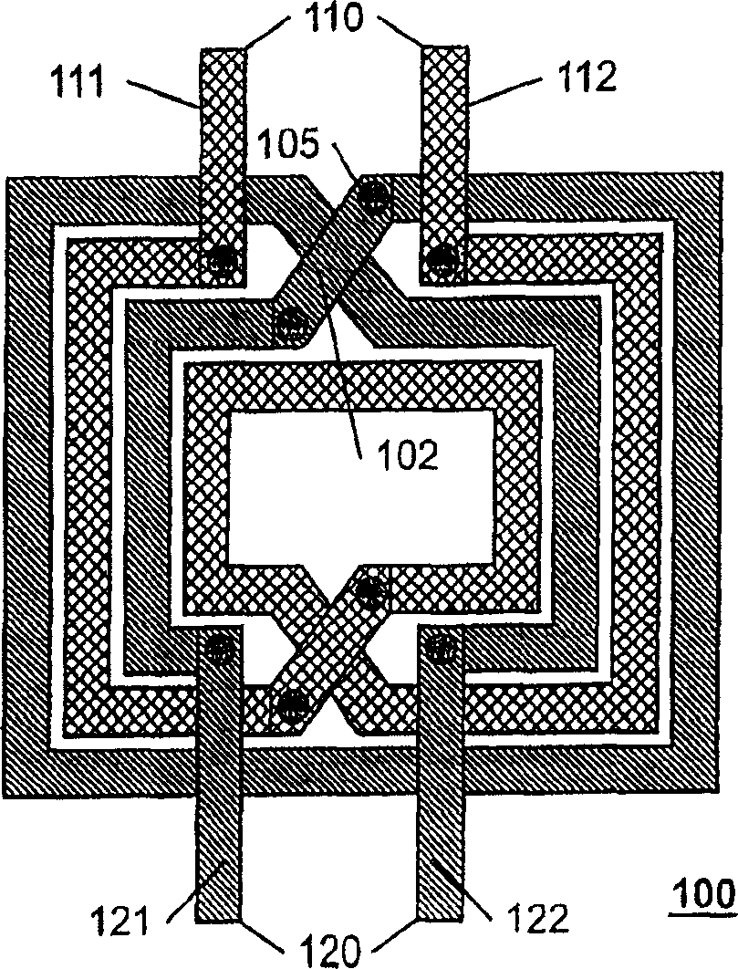
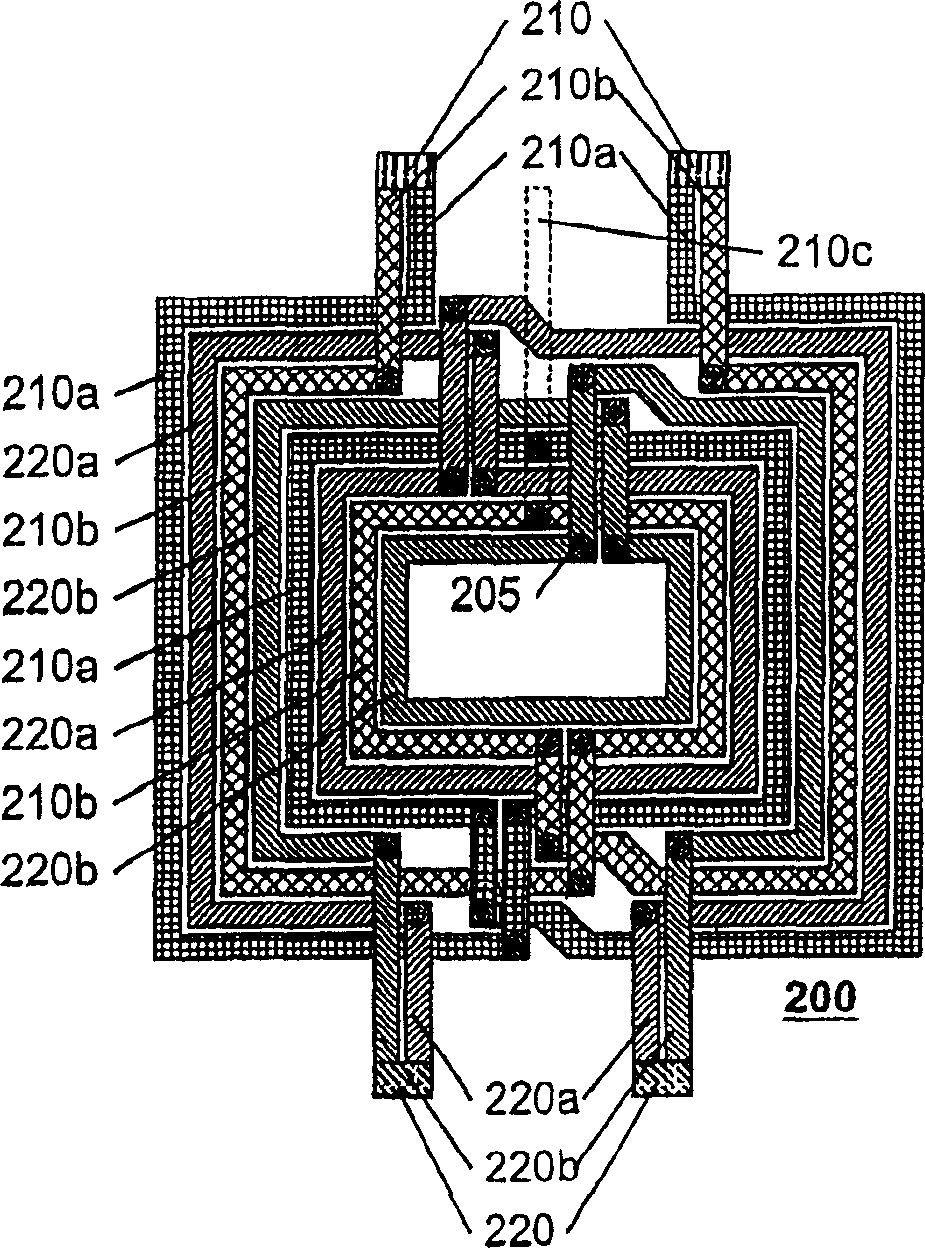
[0015] The present invention seeks to increase inductive coupling between transformer coils without significantly increasing capacitive coupling between coils. To minimize capacitive coupling, the coils are preferably located in a common plane or layer so that virtually only the edges of the conductors in the coils contribute to the capacitance between the coils. To increase inductive coupling, multiple coil sections are used to form each of the transformer primary and secondary coils. Each of the plurality of coil sections is connected in parallel with the other of the plurality of coil sections forming the primary or secondary coil of the transformer.

[0016] If the same number of equal-sized conductor windings are used in each of the multiple coil sections as used in conventional transformer coils, the arrangement of multiple coil sections instead of a single coil takes up more area than a conventional interleaved transformer . It is well known that the resistance per un...


PUM


Abstract

Each coil of a transformer is partitioned into two or more parallel segments. The multiple segments of each coil are interleaved with each other to form a coplanar interleaved transformer that has a greater coupling efficiency than a non-segmented coplanar interleaved transformer. In a preferred embodiment, the multiple segments are of reduced width, so that the interleaved coils consume substantially the same area as the non-segmented coplanar interleaved transformer, thereby maintaining the same inductance as the non-segmented transformer. To provide for maximum efficiency, each segment of each coil is embodied so as to have substantially equal length as each other segment of the coil.

Description

Background of the invention [0001] The invention relates to the field of integrated circuits, in particular to the design of an interleaved transformer device with improved coupling characteristics. [0002] The transformer consists of two coils of electromagnetically coupled wire. An AC signal applied to one of the coils of wire, commonly referred to as the primary coil, induces a corresponding AC signal on the other coil, commonly referred to as the secondary coil. The coupling efficiency between coils determines the efficiency of energy transfer from one coil to another, as well as the overall noise sensitivity of the transformer. [0003] Transformers are commonly used to provide electrical isolation between signals, often taking into account voltage reference plane variations. Transformers are also commonly used to couple signals into resonant inductor-capacitor circuits, with one of the transformer coils providing the inductance, or part of it. Radio frequency (RF) tr...

Claims


Application Information

Patent Timeline
Patent Type & Authority Applications(China)
IPC IPC(8): H01F19/00H01F17/00H01F27/28
CPCH01F27/2804H01F17/0006H01F2021/125H01L28/10H01F27/28
Inventor H·A·维泽尔
Owner KONINKLIJKE PHILIPS ELECTRONICS NV
Learn More