
Fuel distribution device for fuel feed ducts, and fuel supply device with the fuel distribution device

A fuel supply and fuel distribution technology, which is applied in the field of fuel distribution devices in fuel supply pipelines, can solve problems such as coal concentration cannot be adjusted, gas temperature drops, etc., and achieve the effect of easy adjustment and increased concentration

Inactive Publication Date: 2004-08-04
BABCOCK HITACHI KK
View PDF0 Cites 9 Cited by
  • Summary
  • Abstract
  • Description
  • Claims
  • Application Information

AI Technical Summary

Problems solved by technology

[0013] the above Figure 27 ~ Figure 29 The problem with the burners 501-507 of the prior art shown and the fuel supply pipes connected to the burners 501-507 is that the coal concentration in the mixed fluid C in the branch pipes attached to the main pipe 4 cannot be adjusted
[0029] However, if the boiler is switched from the full-load operation state to the part-load operation state, then there is a problem that since the heat entering the furnace 8 is reduced, the temperature of the gas at the furnace outlet of the boiler is reduced, and the temperature of the steam at the boiler outlet is lowered to the steam temperature. The steam temperature required by the buyer-steam turbine inlet (hereinafter sometimes referred to as the steam temperature required by the buyer

Method used


Image

  • Fuel distribution device for fuel feed ducts, and fuel supply device with the fuel distribution device
  • Fuel distribution device for fuel feed ducts, and fuel supply device with the fuel distribution device
  • Fuel distribution device for fuel feed ducts, and fuel supply device with the fuel distribution device

Examples


no. 1 Embodiment

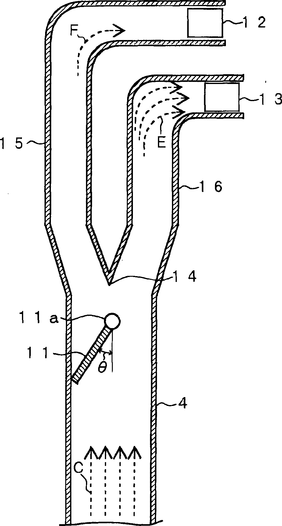
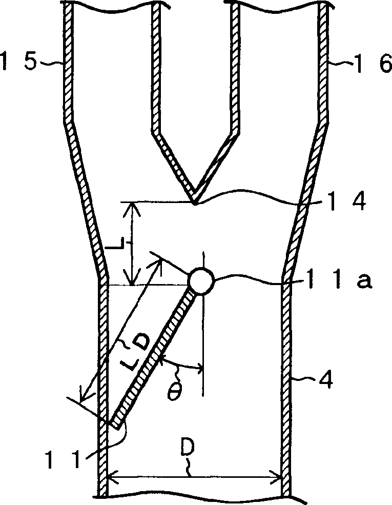
[0091] figure 1 Shown is a cross-sectional view of the main parts of the fuel supply pipe of this embodiment, figure 2 Shown is the configuration in figure 1 A detailed structural drawing around the damper on the fuel supply line.

[0092] figure 1 The fuel supply pipe is branched from the main pipe 4 extending in the vertical direction, the damper 11 arranged at the upstream part near the pipe branch point 14 in the main pipe 4, and the branch connected to the upper burner 12 and the lower burner 13 respectively. The branch pipes 15, 16 etc. constitute.

[0093] Such as figure 2 As shown, on the damper 11 , the damper hinge shaft 11 a is provided near the center of the main duct 4 in a direction crossing the main duct 4 .

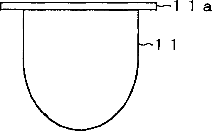
[0094] Such as figure 2 As shown, the present embodiment is an example in which the damper hinge shaft 11 a is provided at the upper end portion of the damper 11 . image 3 Shown is a top view of the damper 11 , the damper 11 is roughly semici...

no. 2 Embodiment

[0097] Figure 4 Shown is a modified example of the first embodiment—a cross-sectional view of the main parts of the fuel supply pipeline of this embodiment, Figure 5 Shown is Figure 4 A top view of the damper. The damper 11 has the same circular shape as the cross-sectional shape of the main duct 4 .

[0098] Also in this case, the damper hinge shaft 11a can be rotated to keep the damper 11 at an appropriate inclination angle θ.

[0099] Image 6 Shown is the coal concentration ratio supplied to the lower burner 13 in the first embodiment and the second embodiment and the length (L1) from the upper end of the damper 11 to the hinge shaft 11a relative to the maximum width (LD) of the damper. The relationship between the value of the ratio (L1 / LD). Also, the coal concentration ratio supplied to the lower burner 13 is the ratio of the coal concentration in the mixed fluid in the main pipe 4 to the coal concentration supplied to the lower burner side branch pipe 16 .

[0...

no. 3 Embodiment

[0112] Figure 9 Shown is an example of a fuel supply pipeline with a rectangular cross section. Its structure is that branch pipelines 15, 16 that are separated from the main pipeline 4 and respectively connected to the upper burner 12 and the lower burner 13 extend upwards side by side. The vicinity of the lower floor burner 12,13 is separated respectively. The damper 11 is arranged in the main duct 4 in front of a branch point which divides into the upper burner 12 and the lower burner 13 .

[0113] Such as Figure 9 As shown, the structure of the damper 11 is to keep the hinge shaft 11a on the upstream side of the vertical line passing through the branch point 14, and the hinge shaft 11a is arranged on the upper end of the damper 11, as Figure 9 As shown, since the damper 11 is inclined to the side of the branch pipe 15 communicating with the upper burner 12, compared with the coal particle concentration in the mixed fluid F passing through the branch pipe 15 communicat...


PUM


Abstract

A fuel distribution device for fuel feed ducts, comprising a branching point in a fuel feeding duct for feeding a mixed fluid of solid fuel and carrier gas to one or more burners installed in the wall surface of a furnace, a plurality of branch ducts branching off from the branching point and having the corresponding burners connected thereto, and a damper disposed in the fuel feed duct on the upstream side of the branching point and capable of changing the angle of inclination with respect to the direction of flow of the mixed fluid in such a manner as to cause the solid fuel concentrations in the mixed fluid fed to the branch ducts to deviate from each other. The angle of inclination of the damper is adjusted to increase the solid fuel concentration of the mixed fluid in a particular burner. The burner having a high solid fuel concentration fed thereto ensures ignition stability and stabilized combustibility of ignited flames during low loading.

Description

technical field [0001] The present invention relates to a fuel distribution device for a fuel supply pipeline, a fuel supply device equipped with the fuel distribution device, and a combustion device equipped with the fuel supply device, and particularly relates to fuel distribution of a fuel supply pipeline suitable for improving the combustion performance of a lignite incineration boiler device. Background technique [0002] Figure 20 Shown is an example of a lignite fired system for an existing boiler. The lignite combustion system and the boiler structure are composed of: a coal hopper 1 and a mill 3 for pulverizing the coal supplied from the coal hopper 1; and a mixed fluid consisting of the coal particles supplied from the mill 3 and the gas for transporting the coal particles (Hereinafter, the coal particles may be referred to as pulverized coal, and the mixture of coal particles and coal particle transport gas may be referred to as mixed fluid or solid-gas two-phas...

Claims


Application Information

Patent Timeline
Patent Type & Authority Applications(China)
IPC IPC(8): F23C5/28F23C7/00F23K3/02
CPCF23K3/02F23K2203/105F23K2203/201F23K2201/30F23C7/008F23C5/28
Inventor 大谷义则吉回秀久金本浩明竹野丰下郡嘉大津村俊一高桥芳孝酒井和人
Owner BABCOCK HITACHI KK
Learn More