
Golf head and connecting method of its surface plate

A golf head and panel technology, applied to golf balls, golf clubs, rackets, etc., can solve problems such as deformation, center of gravity displacement, heat source dispersion of welding bead, etc.

Inactive Publication Date: 2004-08-04
李孔文 +1
View PDF0 Cites 2 Cited by
  • Summary
  • Abstract
  • Description
  • Claims
  • Application Information

AI Technical Summary

Problems solved by technology

[0004] However, this combination method has gaps due to the combination of the hole on the ball head panel and the batting panel. Generally, argon welding is used for welding; while argon welding requires a higher temperature, but the weld bead is shallower and the heat source is weaker. It is scattered and weak in strength. Compared with ionized gas PLASMA welding or laser welding, the temperature is lower, the weld bead is deep, the strength is good, and the heat source is concentrated. Compared with the advantages, the effect is not ideal. In addition, argon welding must Injecting solder all the time is more likely to cause the welding bead to flow into the ball head, resulting in uneven weight of the ball head and displacement of the center of gravity, so that the ball head cannot get the proper hitting stability when hitting the ball; if the welding effect is less A good combination of ionized gas PLASMA welding or laser welding must be seamless to achieve a better welding effect. However, most of the existing ball joints are manufactured by precision casting, and there will be some slight gaps in the manufacturing process. The deformation of the part causes gaps; therefore, the direct use of ionized gas PLASMA welding or laser welding is not ideal in effect

Method used


Image

  • Golf head and connecting method of its surface plate
  • Golf head and connecting method of its surface plate
  • Golf head and connecting method of its surface plate

Examples


Embodiment approach

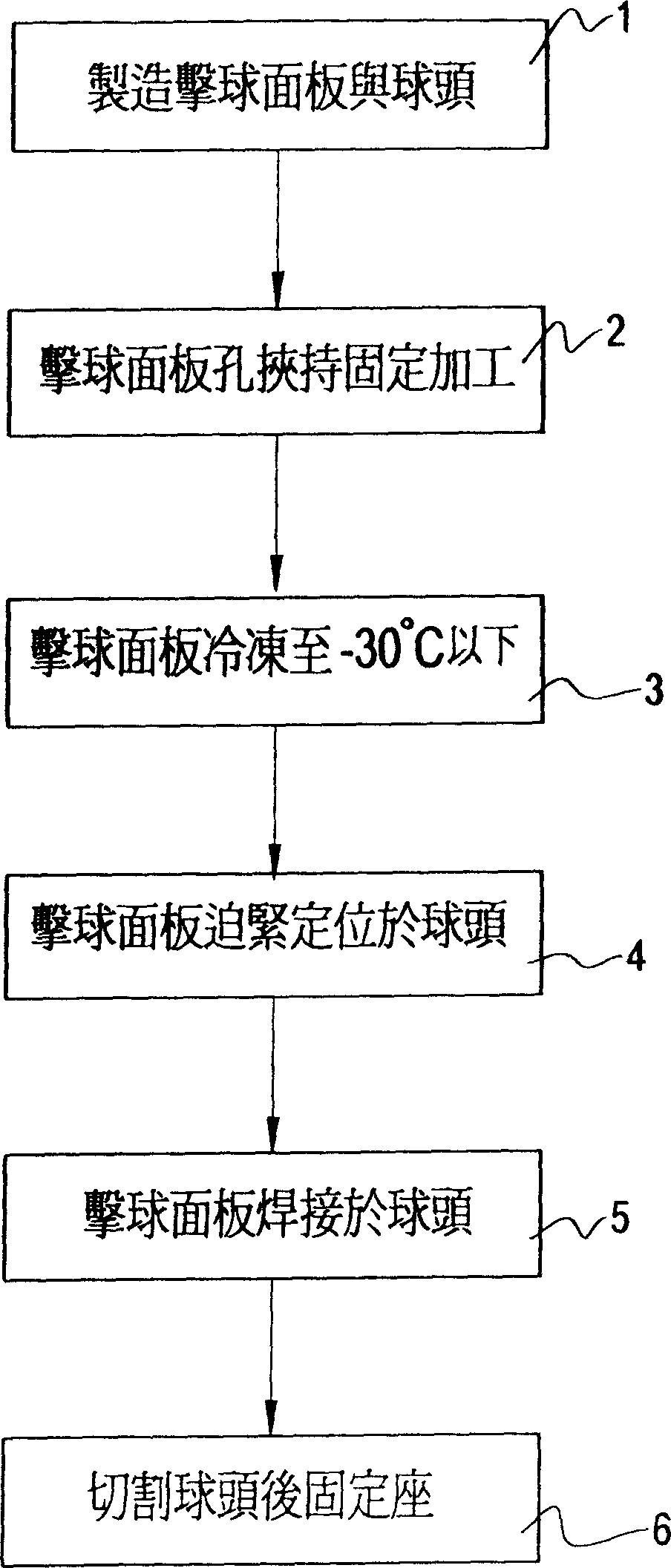
[0027] see now figure 1 As shown, it is a schematic flow chart of the steps of the present invention. The present invention includes the manufacturing step 1 of manufacturing the batting panel and the ball head, the clamping and fixing step 2 of the batting surface processing, the freezing step 3 of freezing the panel, and the frozen rear panel. Step 4 of combining with the ball head, welding step 5 of welding the panel and the ball head, and step 6 of fixing the seat after cutting the ball head.

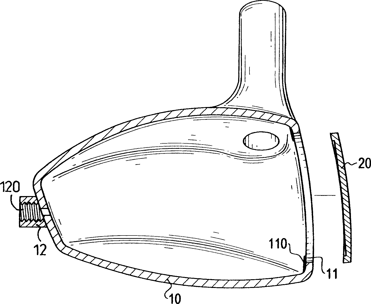
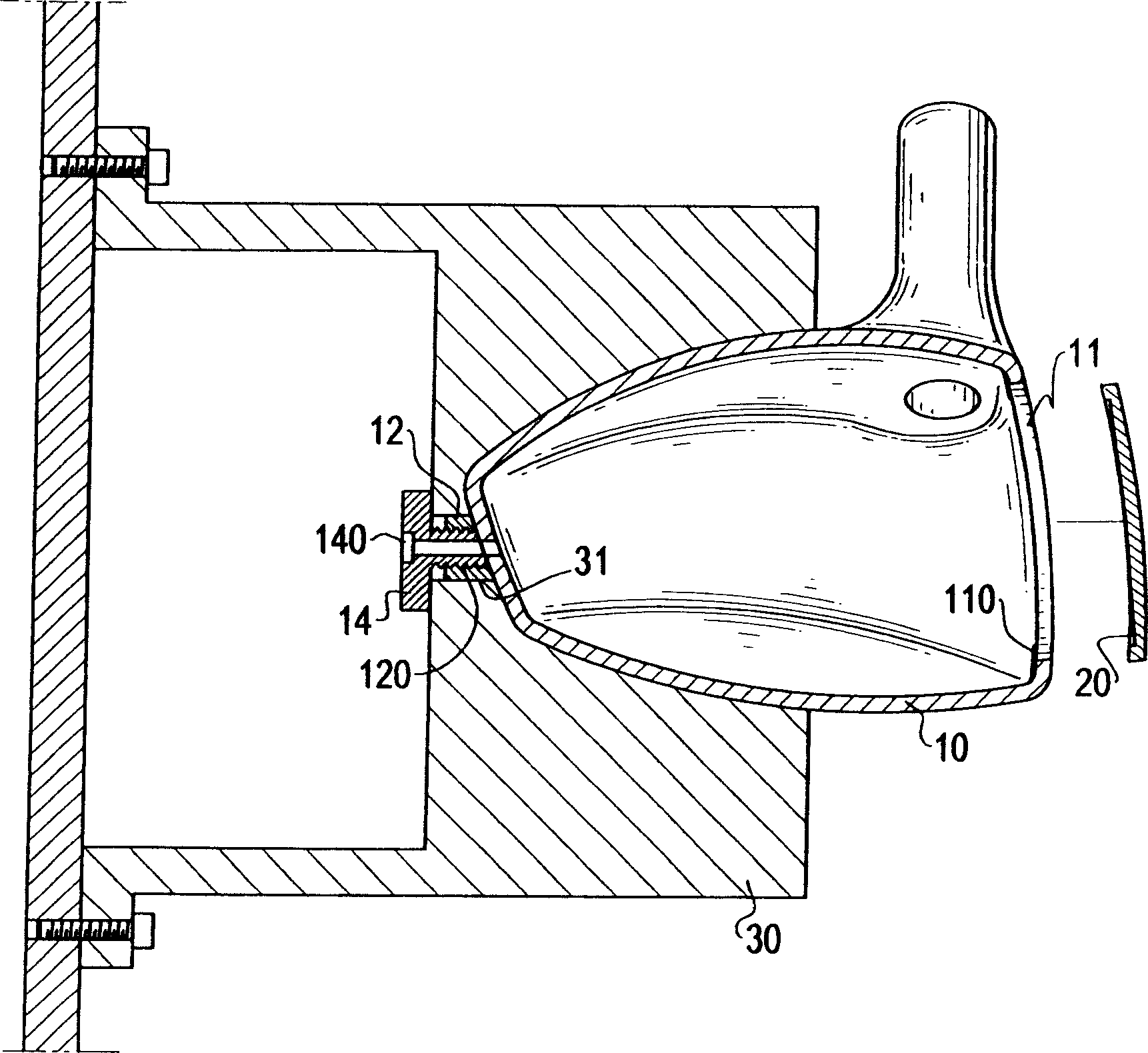
[0028] The manufacturing step 1 is to use the traditional precision machining method to manufacture the ball head and the panel first, the ball head is formed with a panel setting hole for setting the panel, and a screw thread is formed inside and extends outward relative to the other side of the panel setting hole. The fixing seat of the through hole communicating with the inside of the ball head, and the ball head is provided with a protrusion protruding toward the inside of the p...


PUM


Abstract

A technology for welding the golf head with its panel without the welded seam projected inward, which can cause weight nonuniformity and gravitational center shift includes such steps as manufacturing the golf head with a recess for the panel and the panel, fixing the head, freezing the panel, assembling the panel to said recess, naturally restoring the temp of panel for tight match between head and panel, and plasma welding or laser welding.

Description

【Technical field】 [0001] The present invention relates to a combination method of a golf head and its panel, in particular to a method for welding the golf head and the panel so that the weld bead does not protrude from the inside of the ball head, resulting in uneven weight of the ball head and A method of combining a golf head and its faceplate in which the center of gravity displacement phenomenon occurs. 【Background technique】 [0002] Golf has gradually become a popular sports and leisure activity in the recent society, and due to the popularization of golf, golf equipment has gradually been paid attention to. Among the golf equipment, the most important golf club is the most important one. The good level of a club is the stability when hitting the ball and the flight state of the ball after hitting the ball, and the middle level of the club is the result of hitting the ball. The worst is the head at the end of the club. [0003] The structure of the ball head include...

Claims


Application Information

Patent Timeline
Patent Type & Authority Applications(China)
IPC IPC(8): A63B53/04A63B102/32
Inventor 曾文正
Owner 李孔文
Learn More