Rotary compressor
A rotary compressor and compression mechanism technology, applied in the direction of rotary piston machines, rotary piston pumps, rotary piston/swing piston pump components, etc., can solve the problem of low compressor efficiency, fast ejected gas flow rate, Problems such as peak pressure rise, to achieve the effect of suppressing overcompression, improving sealing performance, and preventing power loss from increasing
- Summary
- Abstract
- Description
- Claims
- Application Information
AI Technical Summary
Problems solved by technology
Method used
Image
Examples
Embodiment approach 1
[0060] Hereinafter, Embodiment 1 of the present invention will be described in detail with reference to the drawings.
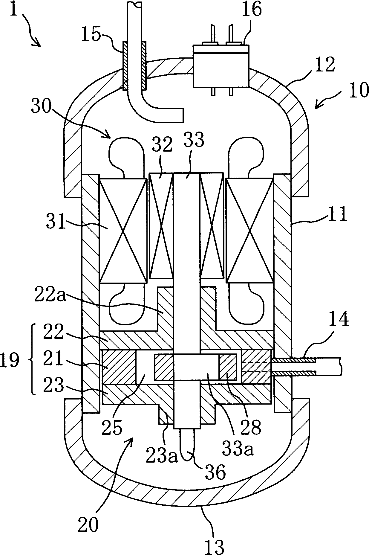
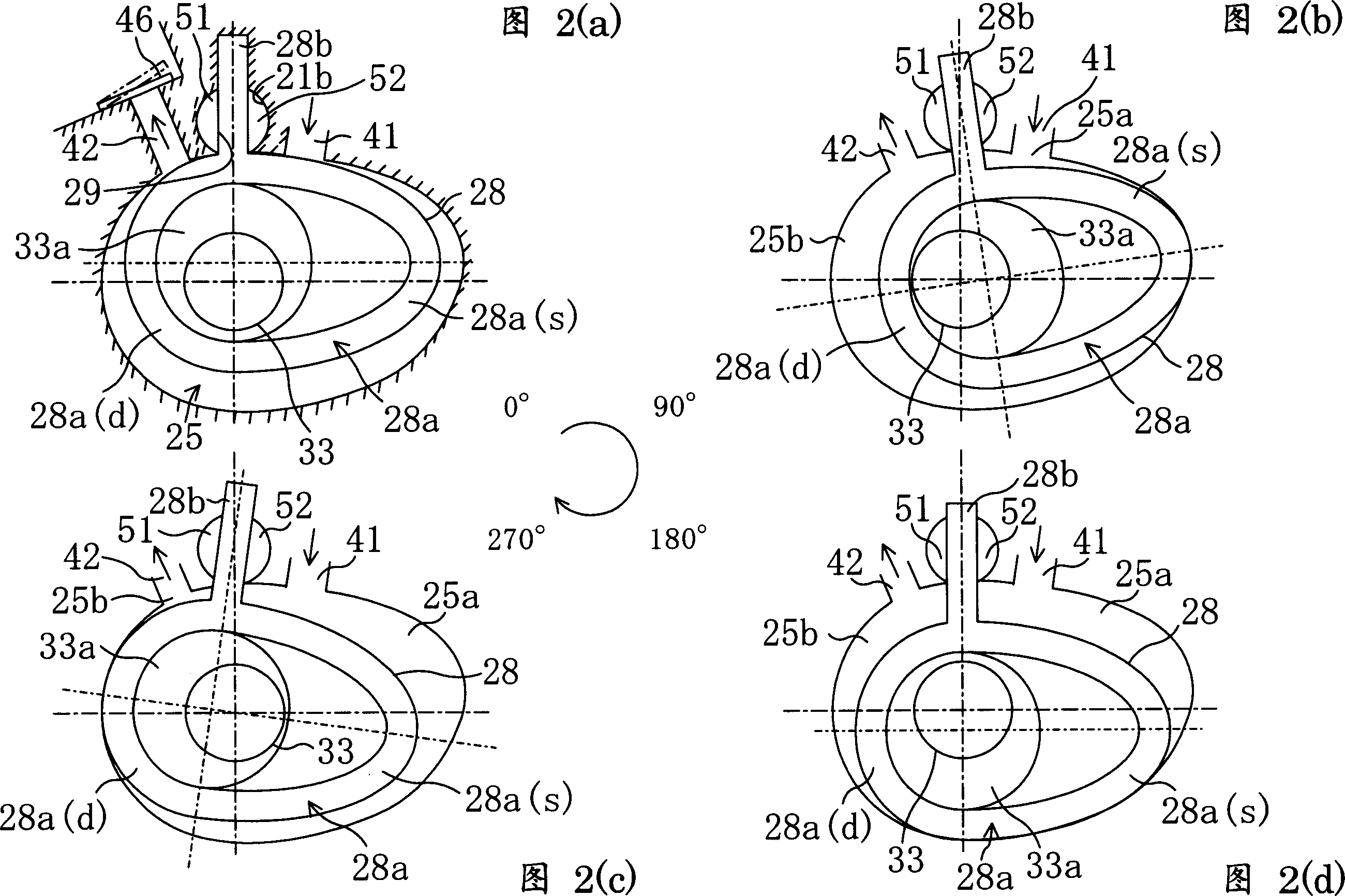
[0061] Such as figure 1 As shown in FIG. 2 , the rotary compressor ( 1 ) of Embodiment 1 is a so-called swing compressor. This compressor (1) accommodates a compression mechanism (20) and a compressor motor (30) in a casing (10), and is constituted as a fully hermetic compressor. The above-mentioned compressor (1) is installed, for example, in a refrigerant circuit of an air conditioner, and is capable of sucking in, compressing, and then discharging a refrigerant.
[0062] The shell (10) is composed of a cylindrical body part (11) and mirror plates (12, 13) respectively fixed on the upper and lower end parts of the body part (11). At a predetermined position on the carcass part (11) close to the bottom, a suction pipe (14) is provided which runs through the carcass part (11). On the other hand, the upper mirror plate (12) is provided with a discharge pip...
Embodiment approach 2
[0094] Next, Embodiment 2 of the present invention will be described. In this second embodiment, as shown in FIG. 4 , the shape of the outer peripheral surface of the rocking piston ( 28 ) and the shape of the inner peripheral surface of the cylinder chamber ( 25 ) are different from those of the first embodiment.
[0095] The outer peripheral surface of the rocking piston (28) of this embodiment 2 is made into a scroll shape such as an involute with respect to the blade (28b), and the diameter is from the suction side (28a(s)) to the discharge side (28a( d)) gradually becomes smaller.
[0096] In addition, the shape of the inner peripheral surface of the cylinder chamber (25) is made to consider the inclination caused by the rocking motion of the rocking piston (28) on the involute. That is, in this embodiment, the shape of the inner peripheral surface of the cylinder chamber (25) is formed based on the envelope when the rocking piston rocks.
[0097] In addition, in this E...
Embodiment approach 3
[0104] Next, Embodiment 3 of the present invention will be described.
[0105] In Embodiment 3, the basic structure is the same as that of the compressor (1) in Embodiment 1, and only a part of the rocking piston (28) is different. Therefore, in Embodiment 3, the description of the configuration of parts other than the rocking piston (28) will be omitted.
[0106]The rocking piston (28) of Embodiment 3 is as shown in Fig. 5(a) and Fig. 5(b), and a gap is formed on the surface of the front part (22) side and the surface of the back part (23) side. Part (28c). The gap portion (28c) is formed on the suction side (28a(s)) where the amount of protrusion is larger than the discharge side (28a(d)) of the rocking piston (28), and on the discharge side (28a(d)). d)) is not formed.
[0107] In addition, in the above-mentioned embodiments, the material of the rocking piston (28) is not specified, and the rocking piston (28) of the third embodiment uses a metal material with a light sp...
PUM
 Abstract
Description
Claims
Application Information
 - R&D Engineer
- R&D Manager
- IP Professional
- Industry Leading Data Capabilities
- Powerful AI technology
- Patent DNA Extraction
Browse by: Latest US Patents, China's latest patents, Technical Efficacy Thesaurus, Application Domain, Technology Topic, Popular Technical Reports.
© 2024 PatSnap. All rights reserved.Legal|Privacy policy|Modern Slavery Act Transparency Statement|Sitemap|About US| Contact US: help@patsnap.com


