
Radiator

A heat sink and cavity technology, applied in the field of heat dissipation equipment, can solve problems such as increasing the volume of the heat sink

Inactive Publication Date: 2004-06-30
庄福良
View PDF0 Cites 2 Cited by
  • Summary
  • Abstract
  • Description
  • Claims
  • Application Information

AI Technical Summary

Problems solved by technology

However, there is a disadvantage in these two methods, that is, the volume of the heat sink is increased, which deviates from the development goal of computers to be smaller and faster.

Method used


Image

  • Radiator
  • Radiator
  • Radiator

Examples


Embodiment Construction

[0015] The present invention is usually made of metal materials with better thermal conductivity, such as aluminum, aluminum alloy,

[0016] and other materials, and the interior of the radiator is provided with a cavity.

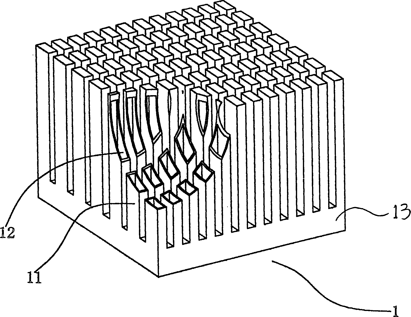
[0017] See attached figure 2 , which is a three-dimensional structure diagram of a specific embodiment of the present invention, which is mainly used for a heat sink on a chip of an integrated circuit, such as a heat sink used by a CPU in a computer mainframe, wherein the cross section of the heat sink 1 base 13 is rectangular , The upper part of the base 13 is provided with several raised square cylinders 12, and the cylinders 12 and the base 13 are solidly integrated. The purpose of setting the columns 12 is to increase the heat dissipation area of ​​the radiator 1 to improve the heat dissipation efficiency.

[0018] See attached image 3 , both the base 13 of the radiator 1 and the inside of the column 12 are cavities 11 , and the cavity inside each ...


PUM


Abstract

The radiator comprises two parts: base and columns. Several raised columns are fixed on the base, and a cavity is provided to connect the base with theses columns. Liquid is filled into the cavity. The liquid filled in the cavity radiates absorbed quantity of heat to raise efficiency of heat dispersion greatly.

Description

Technical field: [0001] The invention relates to the technical field of heat dissipation equipment, in particular to a radiator capable of improving heat dissipation efficiency. Background technique: [0002] The radiator is mainly used in some equipment with high heat generation, which dissipates a large amount of heat generated by the equipment in time to ensure that the equipment can work normally without being damaged. In order to ensure that the heat can be conducted in time, one method usually adopted is to increase the effective heat dissipation area of ​​the radiator. This method is widely used in daily life, for example: the radiators used for heating in winter, the engine radiators of automobiles, etc., are all equipped with more sheets for heat dissipation to increase the heat dissipation of the radiator area, thereby improving heat dissipation efficiency. See attached figure 1 , this is a heat sink 01 for computer CPU, which is usually made of metal materials ...

Claims


Application Information

Patent Timeline
IPC IPC(8): H01L23/367
Inventor 李青容
Owner 庄福良
Learn More