
Digital resistance type contact panel

A touch panel, digital resistance technology, applied in the direction of electrical digital data processing, input/output process of data processing, instruments, etc., can solve the problems of narrowing the size of the field of view 10, signal distortion, disadvantages, etc.

Inactive Publication Date: 2004-06-09
LG DISPLAY CO LTD
View PDF0 Cites 71 Cited by
  • Summary
  • Abstract
  • Description
  • Claims
  • Application Information

AI Technical Summary

Problems solved by technology

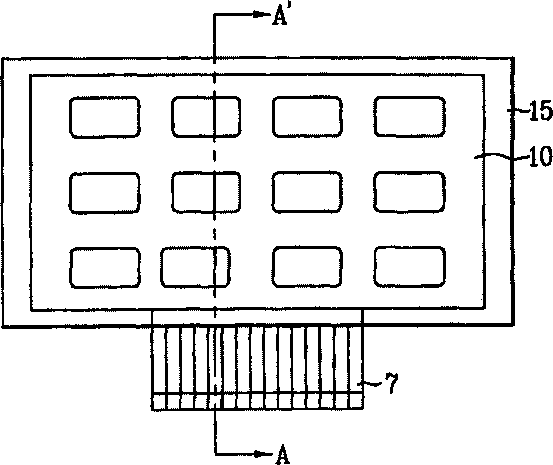
[0017] However, the above-mentioned prior art digital resistive touch panel still has disadvantages, because the plurality of first and second signal lines 7a and 7b must supply voltage signals to the respective patterned transparent electrodes 40 and 30, wherein the plurality of signal lines 7a and 7b are connected to the FPC film set on the side of the touch panel
In this way, an excessively large shadow area 15 is required to accommodate a plurality of first and second signal lines, and the size of the field of view 10 will be unfavorably reduced.
In addition, if you press Figure 3A and 3B As shown, multiple signal lines are arranged along one direction, and the signal line connected to the patterned transparent electrode farthest from the FPC will be longer than the other signal lines, resulting in distortion of the transmitted signal

Method used


Image

  • Digital resistance type contact panel
  • Digital resistance type contact panel
  • Digital resistance type contact panel

Examples


Embodiment Construction

[0040] Preferred embodiments of the present invention illustrated in the accompanying drawings will be specifically described below. Wherever possible, the same reference numbers will be used throughout the drawings to refer to the same or like parts.

[0041] According to the principles of the present invention, the touch panel can be integrated with a display device such as a liquid crystal display (LCD) device. However, the principles of the present invention are obviously easily extended to integrate such touch panels with essentially any type of display device, such as cathode ray tubes (CRTs), plasma display panels (PDPs), electroluminescent displays ( ELD), Vacuum Fluorescent Display (VFD), etc.

[0042] Figure 4A and 4B A plan view showing upper and lower substrates and a plurality of patterned transparent electrodes according to the principles of the first embodiment of the present invention. Figure 5 express Figure 4A and 4B A cross-sectional view taken alon...


PUM


Abstract

A digital resistive-type touch panel includes first and second transparent substrates opposing each other; a plurality of first transparent electrodes extending along a surface of the first transparent substrate; a plurality of second transparent electrodes extending along a surface of the second transparent substrate, wherein the first and second transparent electrodes cross each other; a first signal line for dividing an applied voltage and applying unique voltages to respective ones of the first transparent electrodes; and a plurality of second signal lines connected to respective ones of the plurality of second transparent electrodes.

Description

[0001] This application claims the benefit of Korean Patent Application No. P2002-72351 filed on November 20, 2002, the entire contents of which are hereby incorporated by reference. technical field [0002] The present invention relates to a digital resistive touch panel. The present invention specifically relates to a digital resistive touch panel capable of increasing the ratio of viewing area to dead space. Background technique [0003] Information devices such as personal computers, removable transmission devices, etc. employ various input devices such as keyboards, mice, digitizers, etc. to perform text and other graphic processing. As the demand for information devices that are mobile and easy to use is increasing, in order to develop input devices that are easier to carry and operate than conventional input devices, substitutes for relatively large input devices such as keyboards and mice have been developed. In particular, a great deal of research has been devoted ...

Claims


Application Information

Patent Timeline
Patent Type & Authority Applications(China)
IPC IPC(8): G06F3/03G06F3/033G06F3/045
CPCG06F3/045G06F3/03
Inventor 洪熙政朴喜正
Owner LG DISPLAY CO LTD
Learn More