Punch press

A technology of punching machine and indenter, applied in the field of punching machine, can solve the problems of complex volume of guide device and driving device, difficulty in ensuring accuracy, and increase in energy consumption, etc., and achieve the effects of improving rigidity, improving centering accuracy, and increasing speed

Inactive Publication Date: 2004-05-12
AMADA CO LTD +1
View PDF1 Cites 3 Cited by
  • Summary
  • Abstract
  • Description
  • Claims
  • Application Information

AI Technical Summary

Problems solved by technology

In JP 7-47140, it is necessary to use two systems of rotary positioning, the rotary table and the rotary drum rotating therein, in order to increase the yield, but it is more difficult to ensure the accuracy
[0007] On the other hand, in the prior art of the above-mentioned type II, the indenter is a component for pressing the punch, which must withstand high loads and has a mechanism for driving up and down. When it is to be moved to the X-axis direction and the Y-axis direction, its The guiding device and driving device required for movement become complicated and bulky, resulting in high cost and increased energy consumption

Method used


Image

  • Punch press
  • Punch press
  • Punch press

Examples


Embodiment Construction

[0039] Hereinafter, embodiments of the present invention will be described in detail with reference to the drawings.

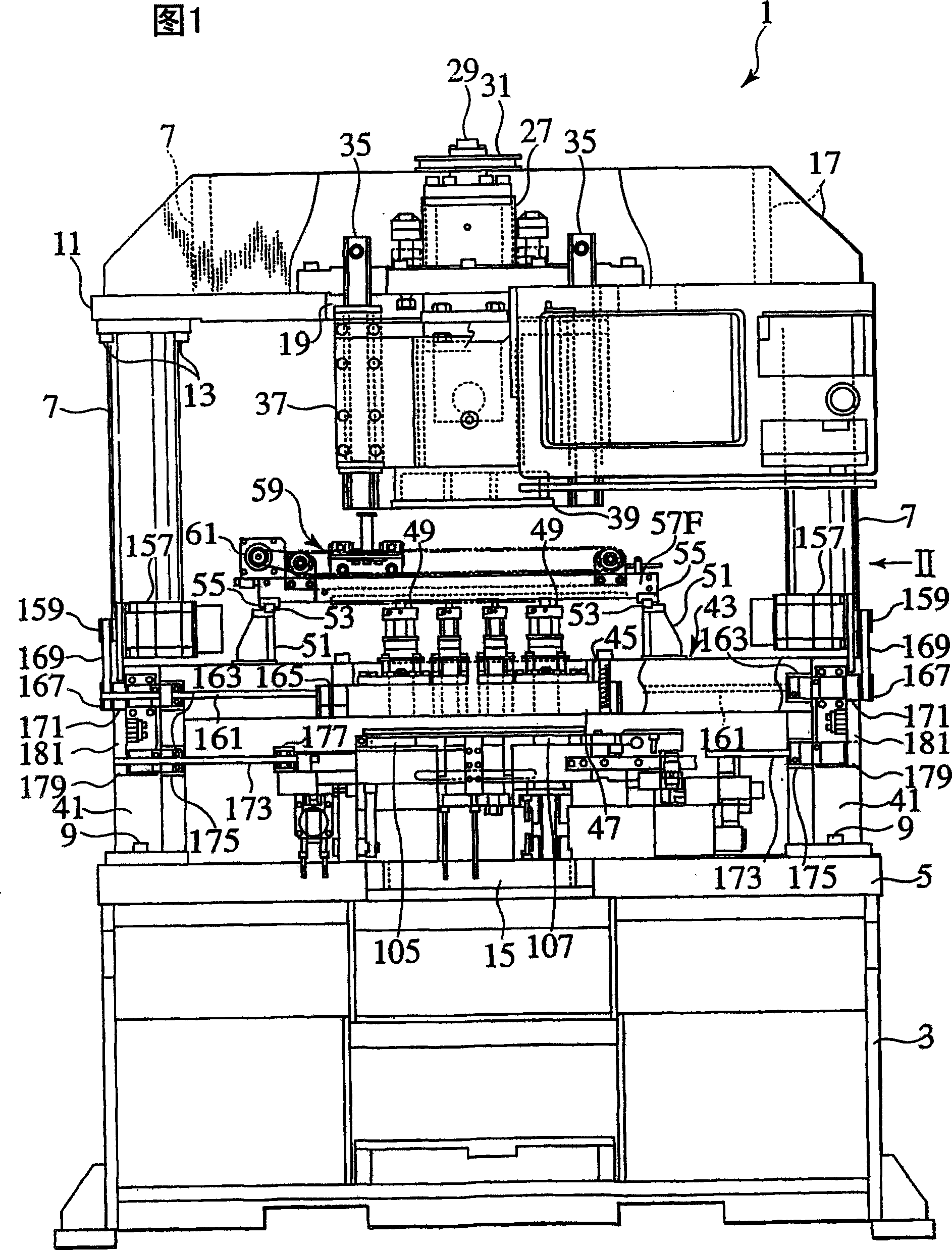
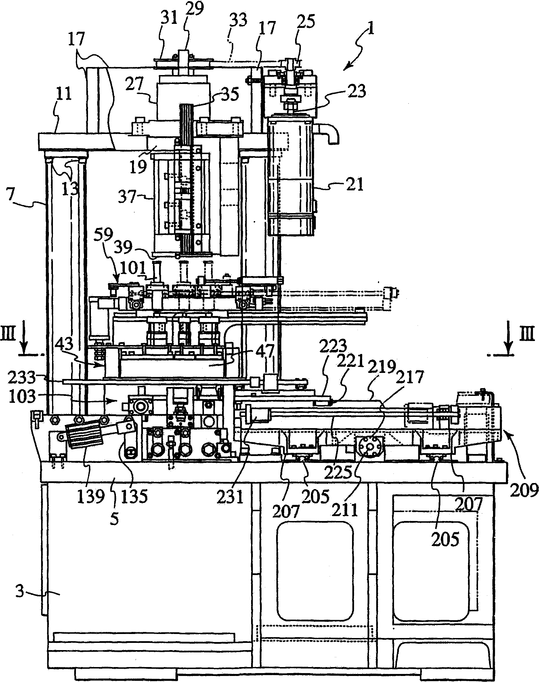
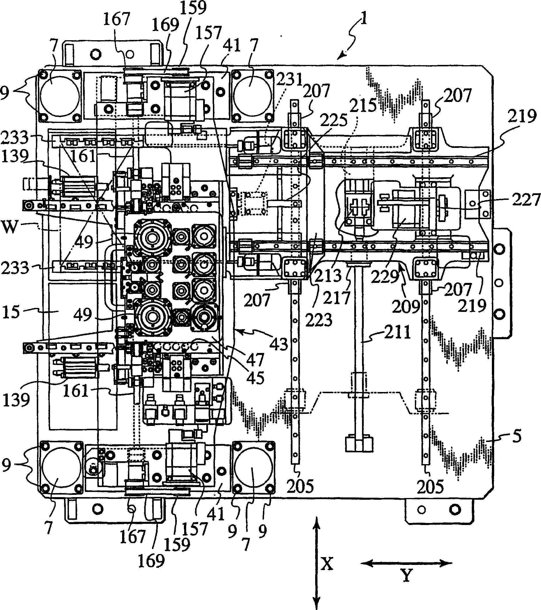
[0040] In Figure 1~ image 3In , the whole of the press machine 1 of the present invention is shown. In this high-precision press machine 1 , a structure is employed to suppress warping and vibration of the overall structure during processing as much as possible. That is, four thick pillars 7 with high rigidity are fixed by bolts 9 on the front, rear, left, and right ends of the thick plate bottom plate 5 provided on the base 3 , and the top plate frame 11 is fixed above the pillars 7 by bolts 9 . In addition, since the recessed portion 15 (see FIG. 7 ) is provided at the center of the front side of the bottom plate 5 , a space under the die holder described later is ensured, and the operator can easily perform die replacement operations.

[0041] On the upper surface of the roof frame 11, reinforcing ribs 17 are provided in front, rear, left, and right, and...


PUM


Abstract

In a cube space having high rigidity, the following members are provided: a die holder (103) which can be pulled out forward, a punch holder (47) fixed to a separate bridge structure, a striker which can be positioned in an XY plane for selecting a desired punch P, a striker supporting frame (59) which can be positioned in the XY plane for selecting a desired punch P and which can slide in a horizontal direction, and a clamp device (232) having clamp arms (233) which are provided with a vertically movable ram (37) and which can enter between the punch holder (47) and the die holder (103) and which hold the opposed ends of the workpiece W. Therefore, it is possible to constitute a punch press (1) which is suitable for precise machining of a thin plate and in which tools can easily be exchanged.A punch press(1), wherein a forwardly withdrawable die holder (103), a punch holder (47) fixed to a bridge structure, a striker support frame (59) allowed to be positioned on an XY plane and allowing the entire body thereof to be slid horizontally to select a desired punch (P), a vertically movable ram (37), and a clamp device (232) having a clamp arm (233) movable into a clearance between the punch holder (47) and the die holder (103) and holding both ends of a work (W) opposed to each other are installed in a space of a highly rigid cubic shape, whereby the punch press (1) suitable for a highly accurate sheet working and not impairing the easiness of metal mold replacement can be formed.

Description

technical field [0001] The present invention relates to a punching machine which presses a punch held on a punch seat by a hammer and cooperates with a die held on the die seat to carry out stamping processing. Background technique [0002] In terms of die selection, conventional press machines include Type I in which the hammer is fixed at a fixed position and a die mounted on a turntable or the like moves, and Type II in which the hammer moves and the die is fixed. [0003] The prior art of Type I has an example of a rotary table press machine in which a mold is mounted on a rotary table, but Japanese Utility Model Publication No. 7-47140 and the like disclose a method of selectively pressing 2 by a single hammer that moves linearly. way of a mold. That is, it is a type in which the rotary positioning of the rotary table is combined with the linear movement of the hammer to finally select the mold. [0004] The prior art of Type II can be said to be a more advantageous t...

Claims


Application Information

Patent Timeline
Patent Type & Authority Applications(China)
IPC IPC(8): B21D28/24B21D37/04B21D43/00B21D43/10B30B15/02
CPCB21D37/04Y10T483/1729B30B15/028B21D28/24
Inventor 德永裕典
Owner AMADA CO LTD
Why Eureka
Try Eureka