
Steering damper apparatus, and method of using same

a technology of steering damper and handlebar, which is applied in the direction of shock absorbers, steering devices, cycle equipments, etc., can solve the problems of excessive easy to kick back, and reduced load on the front wheel, so as to suppress the deflection of the handlebar and the effect of reducing the load on the handlebar

Active Publication Date: 2008-05-27
HONDA MOTOR CO LTD
View PDF15 Cites 17 Cited by
  • Summary
  • Abstract
  • Description
  • Claims
  • Application Information

AI Technical Summary

Benefits of technology

The present invention provides a steering damper for motorcycles that increases the damping force when the motorcycle is driving straight at high speeds. The steering damper apparatus includes a controlling means that adjusts the damping force based on vehicle speed. Specifically, the damping force is fixed at a minimum level when the vehicle speed is equal to or below a first reference speed, and it is fixed at a maximum level when the vehicle speed is equal to or above a second reference speed which is greater than the first reference speed. The controlling means also adjusts the damping force based on acceleration in addition to vehicle speed when the vehicle speed is in an intermediate speed range between the first and second reference speeds. This allows for optimal handling of the motorcycle and suppression of deflection of the handlebar.

Problems solved by technology

In addition, kickback is apt to occur as the load on a front wheel is reduced upon acceleration of the vehicle.
However, in so doing, there may be a case where the steering damper apparatus provides a load on a handlebar which becomes excessive upon a turn in a low speed range when nimble handling is required.
However, the conventional steering damper apparatus, targeted for suppressing deflection of the handlebar in the event of the kickback, cannot always achieve such an effect.

Method used


Image

  • Steering damper apparatus, and method of using same
  • Steering damper apparatus, and method of using same
  • Steering damper apparatus, and method of using same

Examples


Embodiment Construction

[0025]An embodiment will be described below with reference to the drawings.

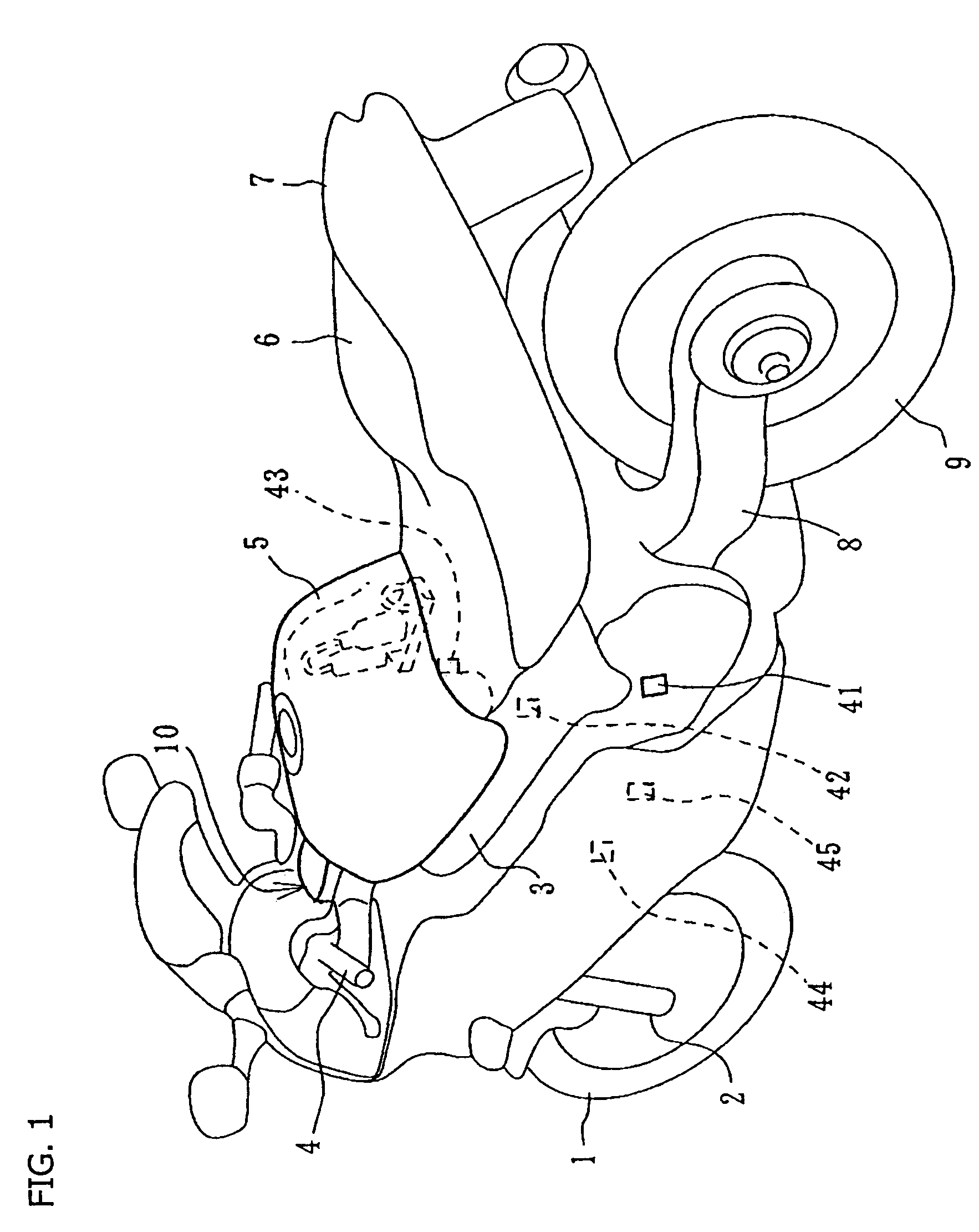
[0026]FIG. 1 is a perspective view of a motorcycle having the inventive steering damper apparatus provided thereon. In FIG. 1, a front fork 2 supports a front wheel 1 at a lower end and is connected at an upper end to a front portion of the motorcycle body frame 3. The front fork 2 is rotated by operation of the handlebar 4. A fuel tank 5 is supported on the vehicle body frame 3. The motorcycle also includes a seat 6, a rear cowl 7, a rear swing arm 8, and a rear wheel 9.

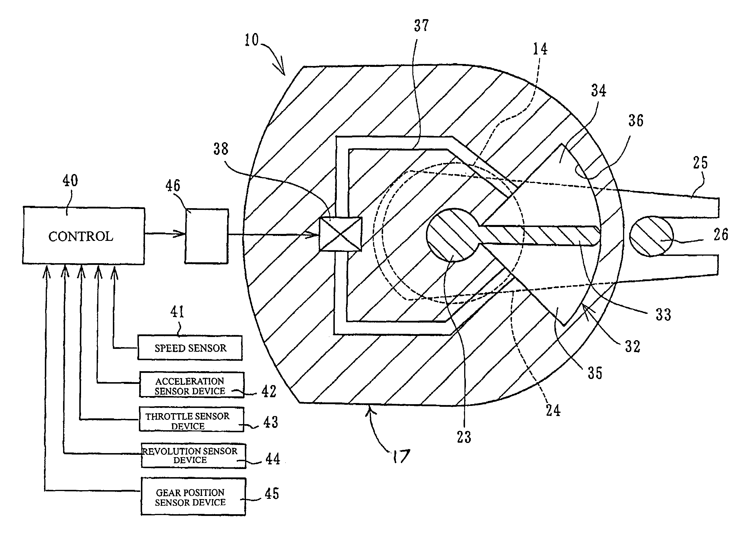
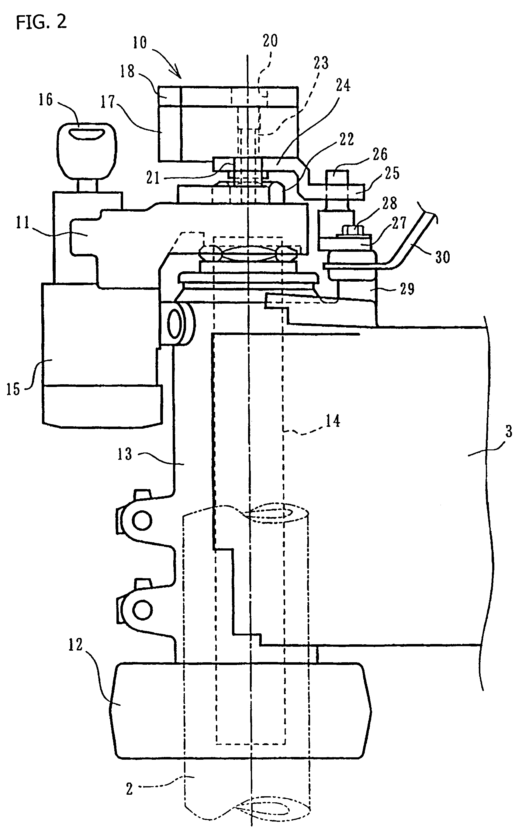
[0027]Next, a steering damper will be described. As shown in FIGS. 2 and 3, a steering damper 10 is provided between a top bridge 11 to which the handlebar 4 is attached, and a front end portion of the vehicle body frame 3. The top bridge 11 is a member which vertically sandwiches, and is thereby integrated with, a steering shaft 14 (indicated by a center line). The top bridge 11 is supported by a head pipe 13 with a bottom bridge 12 placed b...


PUM


Abstract

A steering damper is provided coaxially with a steering shaft, and a handlebar load is provided by causing a variable valve to generate damping force, using rotation of the steering shaft. The damping force is variably controlled in response to vehicle speed. The damping force is fixed to a minimum value C1 for vehicle speeds equal to or below first reference speed V1, fixed to a maximum value C2 for vehicle speeds equal to or above second reference speed V2, and variably controlled in response to vehicle speed and acceleration in an intermediate speed range. Fine maneuverability of a vehicle body is achieved by reducing a load on a handlebar at low vehicle speeds, and a stable movement of the vehicle body is maintained at high vehicle speed by increasing the load on the handlebar and thereby suppressing deflection of the handlebar.

Description

CROSS-REFERENCE TO RELATED APPLICATIONS[0001]The present invention claims priority under 35 USC 119 based on Japanese patent application No. 2004-029443, filed on Feb. 5, 2004. The subject matter of the referenced priority document is incorporated by reference herein.BACKGROUND OF THE INVENTION[0002]1. Field of the Invention[0003]This invention relates to a steering damper apparatus for a motorcycle. More particularly, the present invention relates to a steering damper apparatus in which operation of a steering damper is regulated by an electronic controller to provide a variable damping force, relative to vehicle speed and / or acceleration.[0004]2. Description of the Background Art[0005]A steering damper apparatus configured to generate a damping force against rotation of a steering shaft, to avoid deflection of a handlebar attributable to a kickback upon a disturbance, is well known. Moreover, steering damper devices which provide variable damping forces so as to generate a damping...

Claims


Application Information

Patent Timeline
Patent Type & Authority Patents(United States)
IPC IPC(8): B62K21/00B62K21/08
CPCB62K21/08F16F9/145
Inventor TAKEUCHI, YOSHIAKIONO, MAKOTOMACHIDA, KENICHI
Owner HONDA MOTOR CO LTD
Learn More