Punching/deforming tool for hundle-up device

A technology of stamping tools and strapping devices, which is applied to the parts of strapping machines, strapping objects, manufacturing tools, etc., and can solve problems such as uneven cutting force and unfavorable

Inactive Publication Date: 2004-05-12
ORGAPACK GMBH
View PDF1 Cites 1 Cited by
  • Summary
  • Abstract
  • Description
  • Claims
  • Application Information

AI Technical Summary

Problems solved by technology

[0005] Another problem that can arise with these types of tools is the frequent occurrence of uneven cutting forces
During the sealing operation, varying cu

Method used


Image

  • Punching/deforming tool for hundle-up device
  • Punching/deforming tool for hundle-up device
  • Punching/deforming tool for hundle-up device

Examples


Embodiment Construction

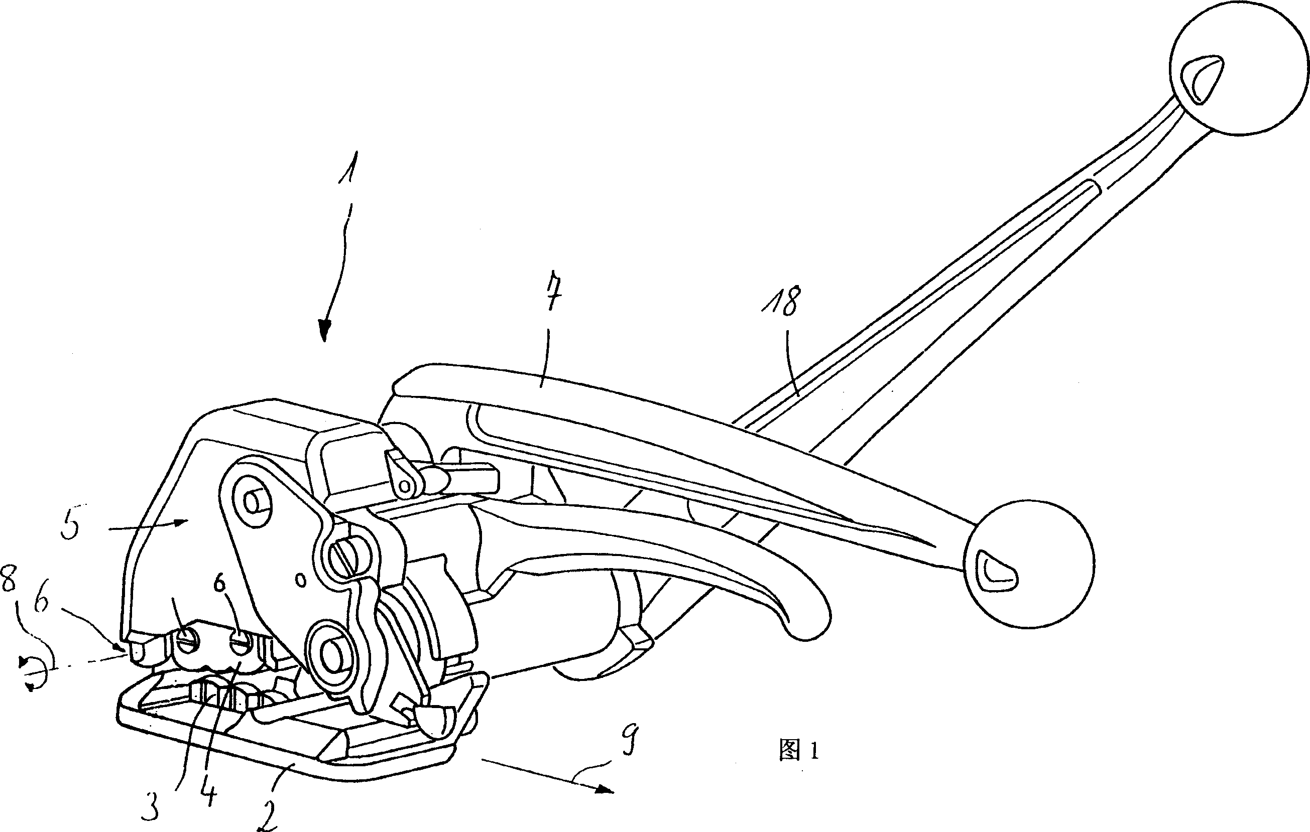
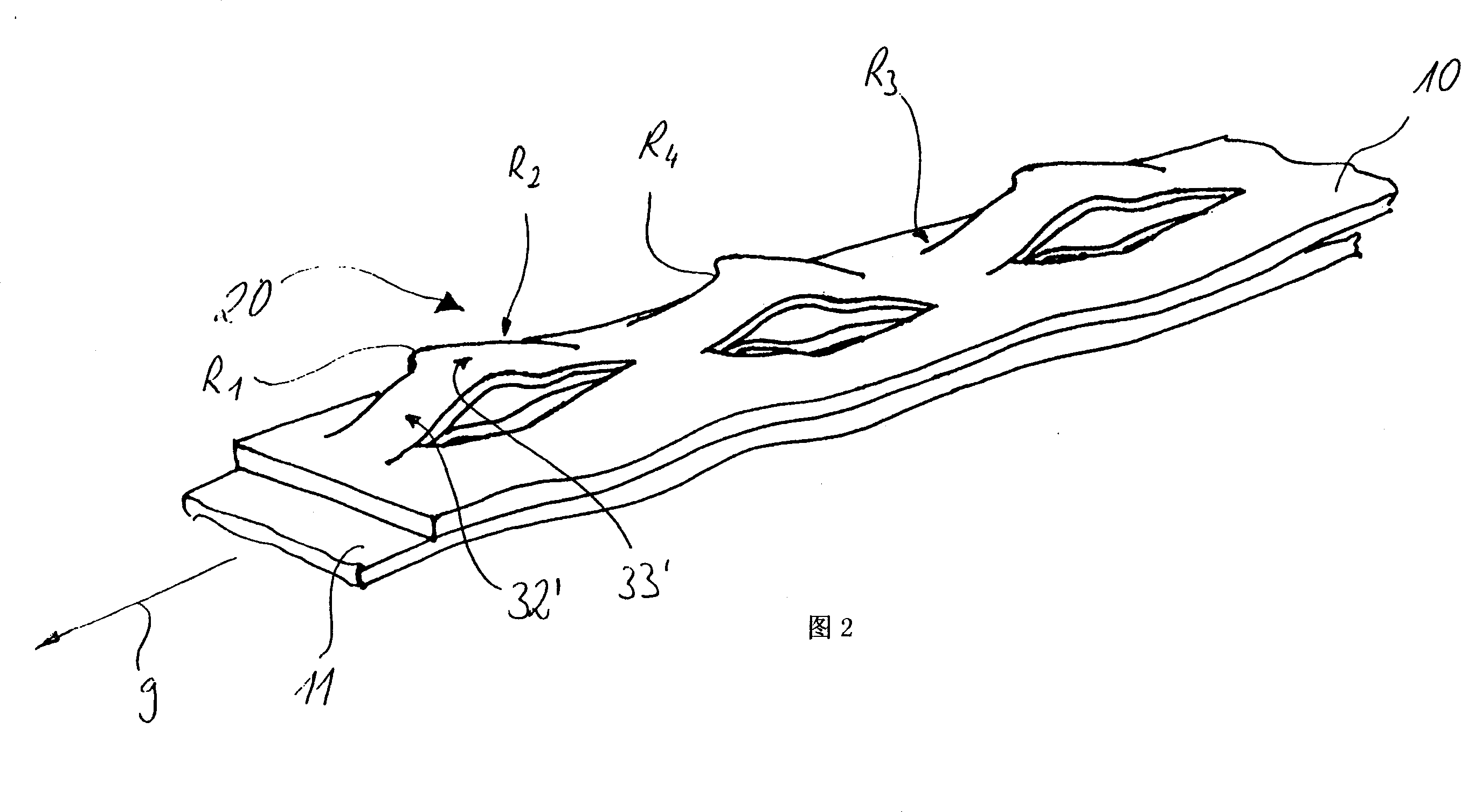
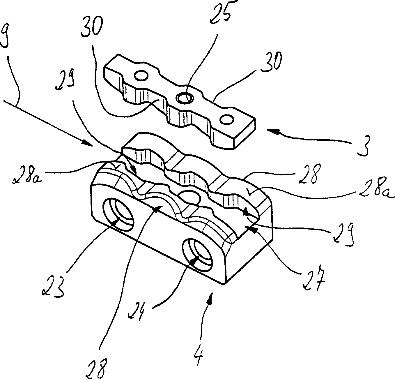
[0020] The manual strapping device shown in FIG. 1 is an example of this type of strapping device to which the present invention is applied. The strapping device is provided with a base plate 2, whose bottom surface is preferably flat, by which the strapping device is placed on the articles to be strapped. The single-part punch 3 is fixed in the base plate 2 . The one-part die 4 interacting with the punch 3 is secured in a die carrier 5 in a detachable manner. The die carrier 5 is pivotably hinged by a rotary hinge 6 (rotation shaft 8 of the hinge 6 is shown in the figure) mounted on the front end of the bottom plate 2 . By turning the lever 7 , the die carrier 5 can be rotated around the axis of rotation 8 in the direction of the bottom plate 2 and can be raised away from the bottom plate 2 . The rotating shaft 8 here basically faces the direction perpendicular to the extending direction 9 of the strapping. During the strapping process, the ends 10, 11 of the two strapping...


PUM


Abstract

Using a punching tool for a strapping unit for producing an auxiliary-free connection of ends of a strapping band, the tool having a recess of different widths, in the case of which at least one section of a recess-bounding wall is provided with a rounded portion in the region of at least one change in width, on the one hand, the intention is to make a fixed closure between the band ends possible. On the other hand, the intention is for this tool to be produced as easily and cost-effectively as possible and, in addition, for uniform cutting forces to be made possible. For this purpose, it is proposed that the rounded portion is of circle-arc shape with a certain radius, and that the largest width of the recess is equal to or less than four times the radius of the wall.

Description

technical field [0001] The invention relates to a stamping / deformation tool for strapping devices for producing an accessory-free connection at the end of a strapping, the tool having a groove of different width, at least one section of the side wall of the groove at least once has a circular portion where the width changes. The invention also relates to a method of making such a tool, as well as the closure itself. Background technique [0002] With the aid of strapping devices, a tensioned strapping loop can be looped around the objects to be strapped, and such strapping devices have been known for some time. This strapping process is performed especially for packaging and shipping purposes. Strapping devices with very different functional principles are already known, in particular for connecting the ends of two strapping straps. The present invention relates to a strapping tool that closes a strap loop by deforming and creating an incision. With this strapping tool, ...

Claims


Application Information

Patent Timeline
IPC IPC(8): B65B13/30
CPCB65B13/305Y10T24/148
Inventor 弗莱维奥·芬佐
Owner ORGAPACK GMBH
Why Eureka
Try Eureka