Photoelectric glass cutting machine

A photoelectric glass and cutting machine technology, applied in glass cutting devices, glass production, glass manufacturing equipment, etc., can solve the problems of fast wear of synchronous belts, high noise, large transmission gap between gears and racks, etc., to achieve uniform cutting force, The effect of low noise and lower production cost

Active Publication Date: 2015-05-13
ANHUI ZHICHENG NC TECH CO LTD
View PDF4 Cites 1 Cited by
  • Summary
  • Abstract
  • Description
  • Claims
  • Application Information

AI Technical Summary

Problems solved by technology

[0002] At present, the cutting machines used for cutting irregularly shaped glass at home and abroad have more and more strict requirements on the thickness of glass cutting and the size of the original sheet. The existing glass cutting equipment is driven by a single rack, the gap between the gear and the rack is large, and the noise is large. Shortcomings such as fast wear of the synchronous belt have gradually failed to meet customer requirements

Method used


Image

  • Photoelectric glass cutting machine
  • Photoelectric glass cutting machine
  • Photoelectric glass cutting machine

Examples


specific Embodiment approach

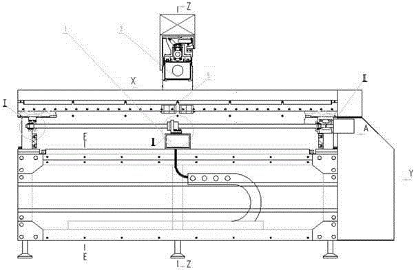
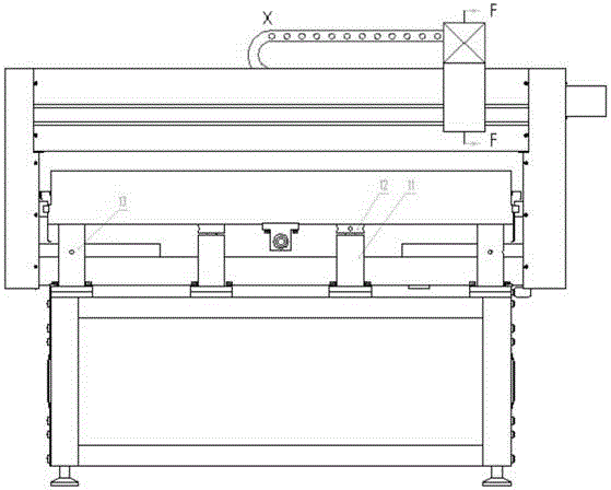
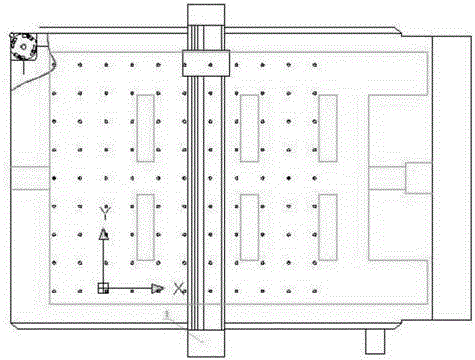
[0022] Such as Figure 1 to Figure 12 As shown, a photoelectric glass cutting machine includes a base 8 made of square tube material, main supports 13 are installed at both ends of the base, a middle support 11 is installed in the middle, and adjustable feet are installed under the base 8 7. The main support 13 is connected to the table 4, the middle support 11 is connected to the base 8, and the adjustment plate 12 is installed on the middle support 11 to make the table 4 flat, and the guide rail 30 is installed on the table 4 , the left middle connecting seat 24 and the right middle connecting seat 34 are installed on the guide rail 30, the left middle connecting seat 24 is connected to the left lower connecting seat 27, and the right middle connecting seat 34 is connected to the right lower connecting seat 37, so The top of the left middle connecting seat 24 is connected with the left upper connecting seat 23, and the right middle connecting seat 34 is connected with the up...


PUM


Abstract

The invention discloses a photoelectric glass cutting machine, relates to the field of glass cutting machinery, overcomes the defects of low efficiency, high consumption and low precision in the prior art, and provides important equipment which can improve labor productivity, cut a plurality of glass different in specification and size, reduce raw material consumption, improve working efficiency and reduce production cost. A to-be-cut raw glass sheet is large in size and to-be-cut glass is required to be thinner and thinner. Through computer automation control and mutual cooperation of three shafts, cutting is uniform in force, stable, quick and small in noise, and a cutting effect cannot be replaced with that of all conventional glass cutting equipment. Especially for ultrathin glass cutting, any shape can be cut, so that the working efficiency is greatly improved.

Description

Technical field: [0001] The invention relates to the field of glass cutting machinery, in particular to a photoelectric glass cutting machine. Background technique: [0002] At present, the cutting machines used for cutting irregularly shaped glass at home and abroad have more and more strict requirements on the thickness of glass cutting and the size of the original sheet. The existing glass cutting equipment is driven by a single rack, the gap between the gear and the rack is large, and the noise is large. Shortcomings such as fast wear of the synchronous belt have gradually failed to meet customer requirements. Therefore, there is an urgent need to develop a low-noise, high-precision, and low-wear glass cutting machine, which can effectively use the original glass sheet to cut glass products of different shapes and sizes, make full use of each original glass sheet, and reduce the loss of leftovers. , Reduce production costs, increase cutting speed and product output. I...

Claims


Application Information

Patent Timeline
Patent Type & Authority Applications(China)
IPC IPC(8): C03B33/02
CPCY02P40/57
Inventor 王留柱张棋瑞
Owner ANHUI ZHICHENG NC TECH CO LTD
Why Eureka
Try Eureka