
Warping machine

A warping machine and warp beam technology, applied in the field of warping machines, can solve the problems of yarn falling off and winding beside the original yarn roll, etc.

Inactive Publication Date: 2004-01-21
LIBA MASCHFAB
View PDF0 Cites 4 Cited by
  • Summary
  • Abstract
  • Description
  • Claims
  • Application Information

AI Technical Summary

Problems solved by technology

However, when running in the reverse direction, the yarn on the support will fall off from some bobbins or be wound next to the original yarn roll

Method used


Image

  • Warping machine
  • Warping machine
  • Warping machine

Examples


Embodiment Construction

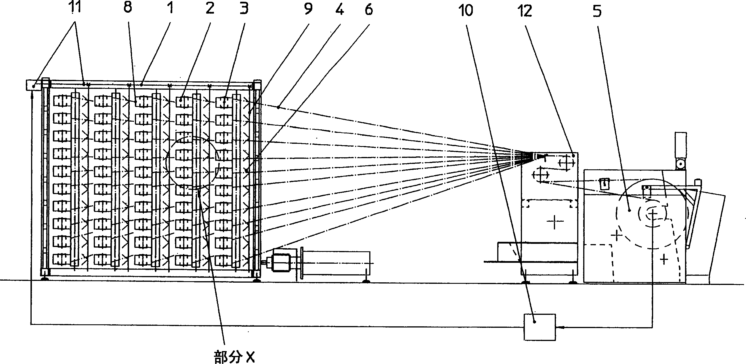
[0023] figure 1 The entire configuration of the warping machine of the present invention is shown in . The warping machine has a bobbin holder 1 , a pre-drawing device 12 and a winding device with a warp beam 5 . The bobbin holder 1 has a plurality of bobbin holders 2 whose axes 3 are oriented vertically and which are fastened to a substantially horizontally arranged bobbin holder. The yarn 4 is drawn from the bobbin 2 and delivered to the warp beam 4 by means of a pre-drawing device 12, said warp beam being pivoted in a device by means of which the warp beam is rotated to achieve the yarn 4 Winding (forward run).

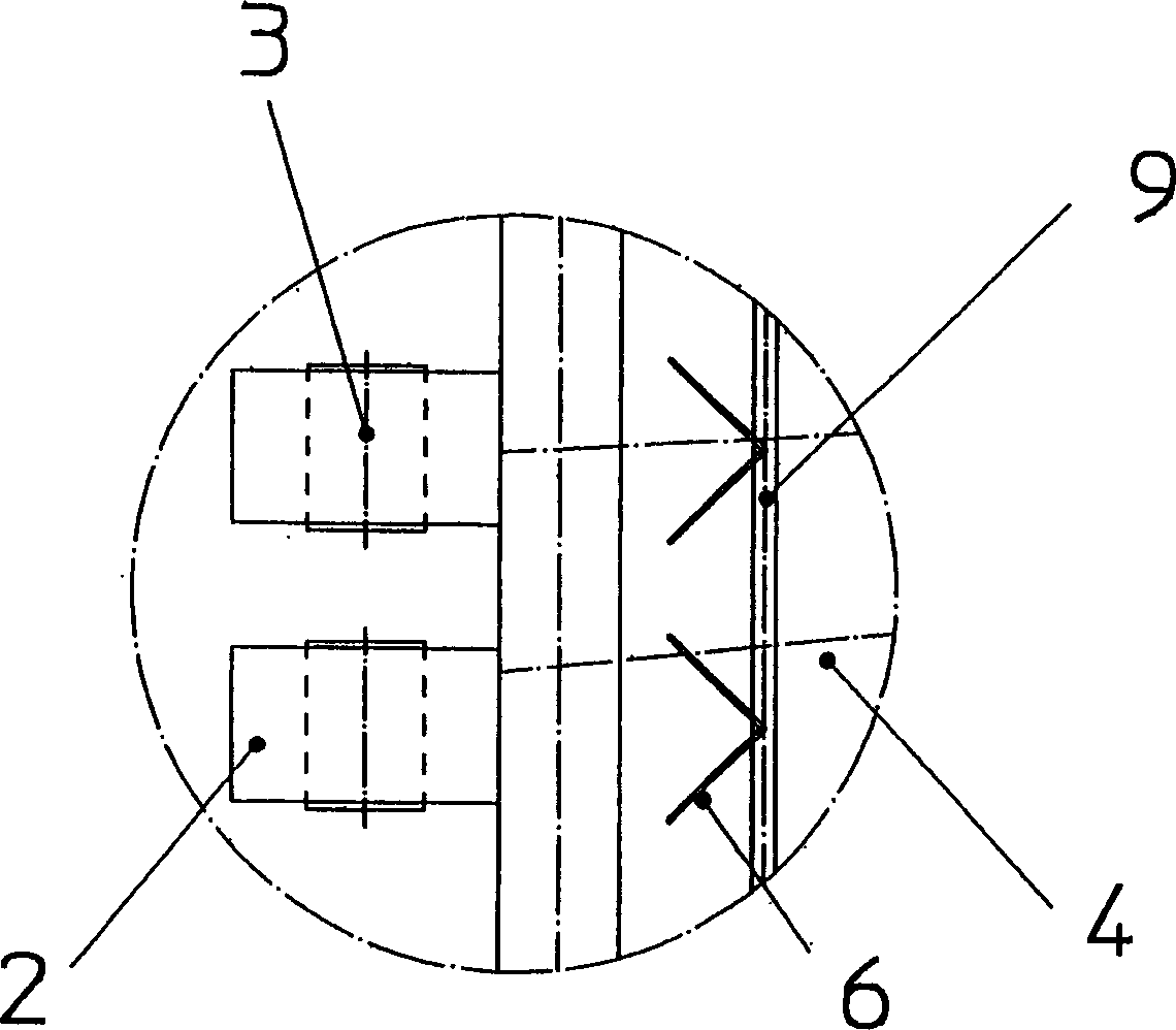
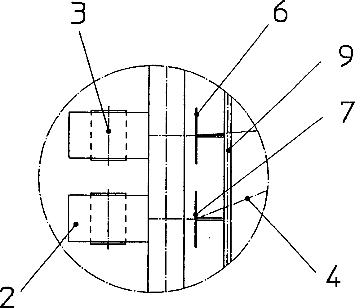
[0024] In addition, the bobbin holder also has a plurality of thread guides 6, the number of which is equal to the number of bobbins provided. The yarn guides 6 are arranged on rods 9 or rails or beams and are respectively located within the area of ​​each bobbin 2 of the bobbin holder 1 . Wherein the yarn guide 6 is fixedly connected with the rod member 9 . A...


PUM


Abstract

The present invention relates to a warping machine having a driven bobbing bracket (1) which is equipped with a plurality of bobbing (2) thereon. The yarns (4) from the bobbing (2) wind at the cane roller (5) (positive direction operation) and unwind from the cane roller (5) to the bobbing (2) especially when yarns break, meaning that the yarns wind at the bobbing (2) (inverted running) again. Each bobbing (2) is equipped with a yarn guide (6) which engage with the yarns (4) during the inverted running. The yarn guide (6) is set with the scope of the reel for yarn of the bobbing (2) when being at the bonding station, then the yarns (4) wind at the direct scope of the reel for yarn of the bobbing (2) again during the inverted running, wherein each member is started-up to maintain the preset pre-unbent yarn velocity of the elastomeric yarns within the length scope of the yarns when a production interrupt occurs.

Description

technical field [0001] The invention relates to a warping machine for elastic yarns, having a bobbin holder with a plurality of bobbins, the yarn of the bobbins wound on the bobbins being stretched by pre-drawing and coiled with a defined pre-tension Winding on a warp beam, the invention also relates to a method for reversing the warping machine. Background technique [0002] Warping machines of this type are known to have a plurality of bobbins which are arranged on bobbin holders. Yarns from the bobbins are wound onto warp beams from which they are then delivered as warp yarns to the knitting or weaving process. Practice has shown that under the situation of having multiple bobbins and multiple yarns, the occurrence of sometimes broken yarn cannot be avoided. In the event of a yarn break, the yarn is bounced in the direction of the support and in the direction of the warp axis due to its internal elasticity. In order to eliminate yarn breaks, the warping machine must be...

Claims


Application Information

Patent Timeline
Patent Type & Authority Applications(China)
IPC IPC(8): D02H1/00D02H3/00D02H13/02D02H13/24
CPCD02H1/00D02H3/02D02H13/24
Inventor 乌韦·弗朗茨
Owner LIBA MASCHFAB
Learn More