
Low temp. floor radiation heating device and mfg. method thereof

A technology of radiant heating and manufacturing method, which is applied in heating methods, hot water central heating systems, household heating, etc., can solve the problems of long production and installation cycle of low-temperature floor radiant heating devices, increase project cost, and complex procedures, and achieve The effect of reducing cost, reducing heat loss, and quick construction and installation

Inactive Publication Date: 2004-01-07
顾世章
View PDF0 Cites 10 Cited by
  • Summary
  • Abstract
  • Description
  • Claims
  • Application Information

AI Technical Summary

Problems solved by technology

Due to the complex process, the different size standards of the construction site, and the mutual influence of various cross operations, the production and installation period of the low-temperature radiant floor heating device is longer, which increases the cost of the project, and the position of the line where the plastic hose is laid has a relatively long time. Large randomness will bring inconvenience to future maintenance and other construction operations

Method used


Image

  • Low temp. floor radiation heating device and mfg. method thereof
  • Low temp. floor radiation heating device and mfg. method thereof
  • Low temp. floor radiation heating device and mfg. method thereof

Examples


Embodiment Construction

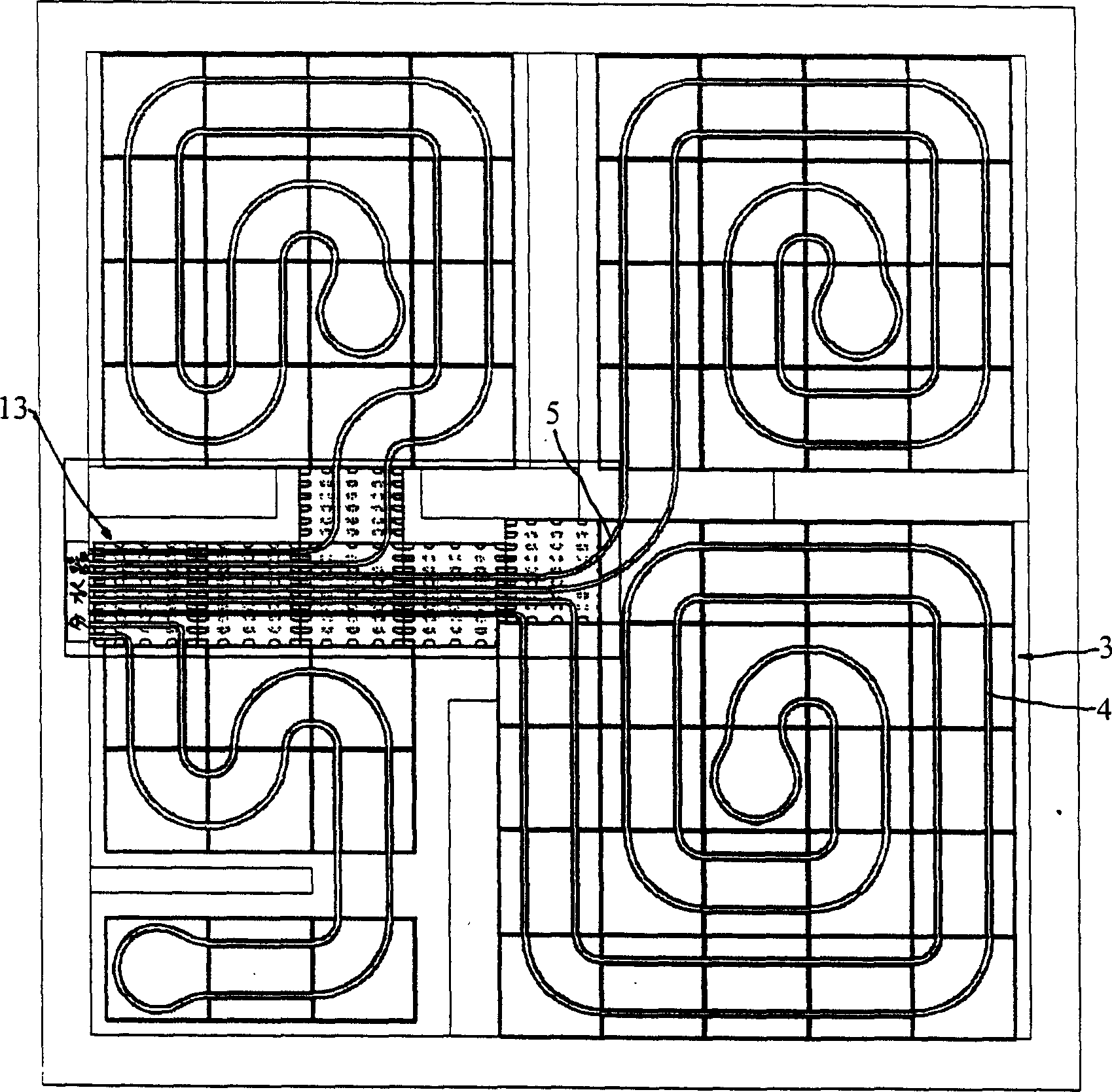
[0026] like figure 1 , figure 2 , Figure 3 and Figure 4 As shown, the low-temperature floor radiation heating device of the present invention includes a hose 5 connected to the heating device, and the hose 5 is made of a plastic pipe or an aluminum-plastic composite pipe. It also includes a heat radiation formwork 3 composed of a heat insulation layer 1 and a light-weight material heat storage layer 2. The heat radiation formwork 3 is rectangular, and several heat radiation formworks 3 are arranged in rows and columns along the floor of the house. The light material heat storage layer 2 is provided with grooves 4, and the turning point of the grooves 4 is arc-shaped. The grooves 4 are connected in series with each other, the hose 5 is arranged in the groove 4, the bead 8 is arranged above the groove 4, and the groove 4 is covered with a concrete layer (not shown in the figure) out), usually by using concrete to smooth the groove 4.

[0027] The heat insulation layer 1 is...


PUM


Abstract

The heating system includes the flexible tubes connected to the heating system and the thermal radiation templates composed of the thermal insulation layer and the heat-collecting zone made from light material. Several pieces of the thermal radiation templates are tiled along rows and columns. There are grooves on the heat-collecting zones. Two ends of the groove are leaded to sides of the thermal radiation templates respectively. The grooves are connected in series. The flexible tubes are setup inside grooves and concrete layers cover grooves. The thermal insulation layer is made from PVC foaming material. Adding the mixed material from cement 20úÑ, fluvial sand 15úÑ, perlite or polystyrene granules 67úÑ and building glue 3úÑ into the grooves makes light heat-collecting zones. The invention provides the heating system built from material with low cost, quick installation and low heat loss in transmission process.

Description

technical field [0001] The invention relates to a low-temperature floor radiation heating device for heating under the ground, ceiling, wall or floor and its manufacturing method. Background technique [0002] According to the traditional Chinese medicine health care theory of "hot feet and cool head", the indoor temperature should be warm at the bottom and cool at the top, which is beneficial to human health. Therefore, existing building heating begins to adopt low-temperature radiant floor heating device step by step, but existing low-temperature radiant floor heating device usually adopts laying insulation layer, reflection layer and laying barbed wire, plastic hose at the construction site, after fixing Fill with pea stone mortar. Due to the complex process, the different size standards of the construction site, and the mutual influence of various cross operations, the production and installation period of the low-temperature radiant floor heating device is longer, whic...

Claims


Application Information

Patent Timeline
IPC IPC(8): F24D3/14
CPCY02B30/00
Inventor 顾世章
Owner 顾世章
Learn More