Lubricant oil pump unit

A lubricating oil pump, lubricating oil technology, applied in the direction of lubricating pump, lubricating pump pressure lubrication, pressure lubricant, etc., can solve the problems of increasing the wear of moving parts, weakening the lubricating power, high viscosity, and achieving simplified structure, light motion quality, Precisely control the effect of lubrication

Inactive Publication Date: 2003-12-17
WILLY VOGEL AG
View PDF1 Cites 4 Cited by
  • Summary
  • Abstract
  • Description
  • Claims
  • Application Information

AI Technical Summary

Problems solved by technology

The varying movement resistance of the working and metering pistons, the friction on the return spring, and the uncontrollable fatigue of the return spring affect the time and course of the return in an uncontrollable manner and are required for certain operating states of the internal combustion engine High lubrication cycle frequency or high lubrication dynamics create mechanical limitations
Ordinary oil circuits have many disadvantages, because the oil used for lubrication is often of high viscosity, poor quality, and often contains many impurities, which increase the wear of moving parts and weaken the power of lubrication

Method used


Image

  • Lubricant oil pump unit
  • Lubricant oil pump unit
  • Lubricant oil pump unit

Examples


Embodiment Construction

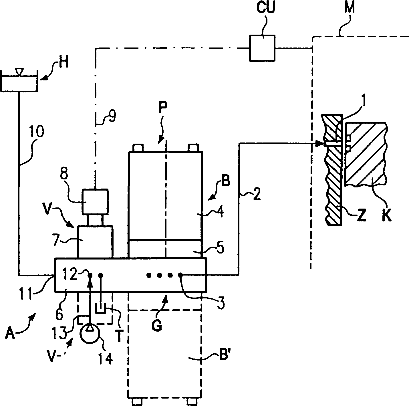
[0030] for the sake of figure 1 Lubricating points 1 on multiple cylinders of the internal combustion engine M such as diesel engines are lubricated, and a cylinder lubrication system A is set up. figure 1 Only one lubrication point 1 on the cylinder is shown in . In the above-mentioned cylinder lubricating system A, a lubricating oil pump unit P is provided to lubricate the cylinder synchronously with the working cycle of the internal combustion engine. That is to say, the lubricant, which is lubricating oil in this example, is precisely and quantitatively supplied to the piston stroke of piston K according to the above-mentioned working cycle, and its supply amount can be determined by the engine control unit CU. When the pad reaches lubrication point 1, it is either slightly ahead or behind, or when the cooling area of ​​the piston is just aligned with lubrication point 1 (depending on the piston stroke). In this case, the lubricating oil pump unit P can be controlled pre...


PUM


Abstract

The invention relates to a lubricant pump unit (P) for lubricating the cylinders in precise time with the cycle in internal combustion engines (M) such as diesel engines. Said pump unit contains a working piston (22), which drives several metering pistons (25) that are allocated to lubricating point connections and can be driven back and forth in feed and return cycles by means of a working stroke that can be adjusted to meter the supply of lubricating oil, a magnetically actuated control valve (V) being provided in a control oil circuit of the working piston. The working piston (22) is subjected in turn to a hydraulic pressure both in the feed cycle and the return cycle by the control oil circuit.

Description

technical field [0001] The invention relates to a lubricating oil pump unit according to the preamble of claim 1 . Background technique [0002] The working piston of the lubricating oil pump unit disclosed in the patent document CH 673 506A is hydraulically driven for its delivery stroke. The return stroke of the working piston is realized by means of a return spring. The metering piston is pushed in the delivery direction by the aforementioned working piston, while the return spring is used for its suction stroke. Lubricating oil is sucked into the quantitative cylinder through the oil inlet valve from an annular chamber, and the above-mentioned annular chamber communicates with an oil tank arranged at a high place. To monitor the function of the pump, the position of the working piston is detected. In addition, there are optical / electrical function monitoring devices working in tandem at least on the ports of some lubrication points. The dosing of lubricating oil is d...

Claims


Application Information

Patent Timeline
Patent Type & Authority Applications(China)
IPC IPC(8): F01M1/08F01M1/16F01M5/00F04B9/105F04B9/113F04B49/06F16N13/04
CPCF01M1/08F16N13/04F01M2001/083F01M1/02
Inventor 迪特尔·W·赫斯扬·勒伊特
Owner WILLY VOGEL AG
Why Eureka
Try Eureka