
Electric upsetter capable of realizing process parameter optimum control

A process parameter optimization, electric upsetting machine technology, applied in mechanical equipment, connecting components, nails, etc., can solve problems such as over-burning, discontinuous control, optimization, etc., to reduce upsetting waste, increase stability, and increase clamping. force effect

Inactive Publication Date: 2003-11-26
GUANGDONG UNIV OF TECH +1
View PDF0 Cites 14 Cited by
  • Summary
  • Abstract
  • Description
  • Claims
  • Application Information

AI Technical Summary

Problems solved by technology

[0002] At present, the intelligence level of electric upsetting machines is low, and the process parameters such as heating current, upsetting pressure, and speed can only be determined by experience in production. The main problems are as follows: (1) Each process parameter (pressure, speed, voltage, etc.) ) is a preset constant in a single working cycle, and parameter optimization cannot be realized; (2) After the working conditions (temperature, wear, blank quality, etc.) change during the working process, the system cannot automatically change to adapt to the changes in working conditions, To ensure the quality of the product; (3) Every time a product is replaced, the process parameters must be readjusted and explored, which not only wastes time, but also causes a lot of waste products, and often occurs overheating, overburning, folding, skewing, cracks, etc.
For this reason, many manufacturers and scientific research institutions at home and abroad have taken great pains and done a lot of work, such as the "parameter analysis and microcomputer control of valve electric upsetting process" disclosed by Yin Ximeng and others in "Forging Technology" 1986 / 4; The "learning-based expert control system for electric upsetting machines" disclosed by Liu Jingyu and others in "Electrical Automation" 1999 / 2; the "group control system for electric upsetting machines" disclosed by Yang Qingyun in "Forging Technology" 1990 / 3; The introduction of automatic control has played a certain role in improving the quality of products, but they also have some shortcomings, such as: discontinuous control, only control part of the electric upsetting process parameters or separation of data acquisition and control, so it is difficult to ensure the quality of control, the most critical Unfortunately, they failed to achieve the optimization of process parameters

Method used


Image

  • Electric upsetter capable of realizing process parameter optimum control
  • Electric upsetter capable of realizing process parameter optimum control
  • Electric upsetter capable of realizing process parameter optimum control

Examples


Embodiment

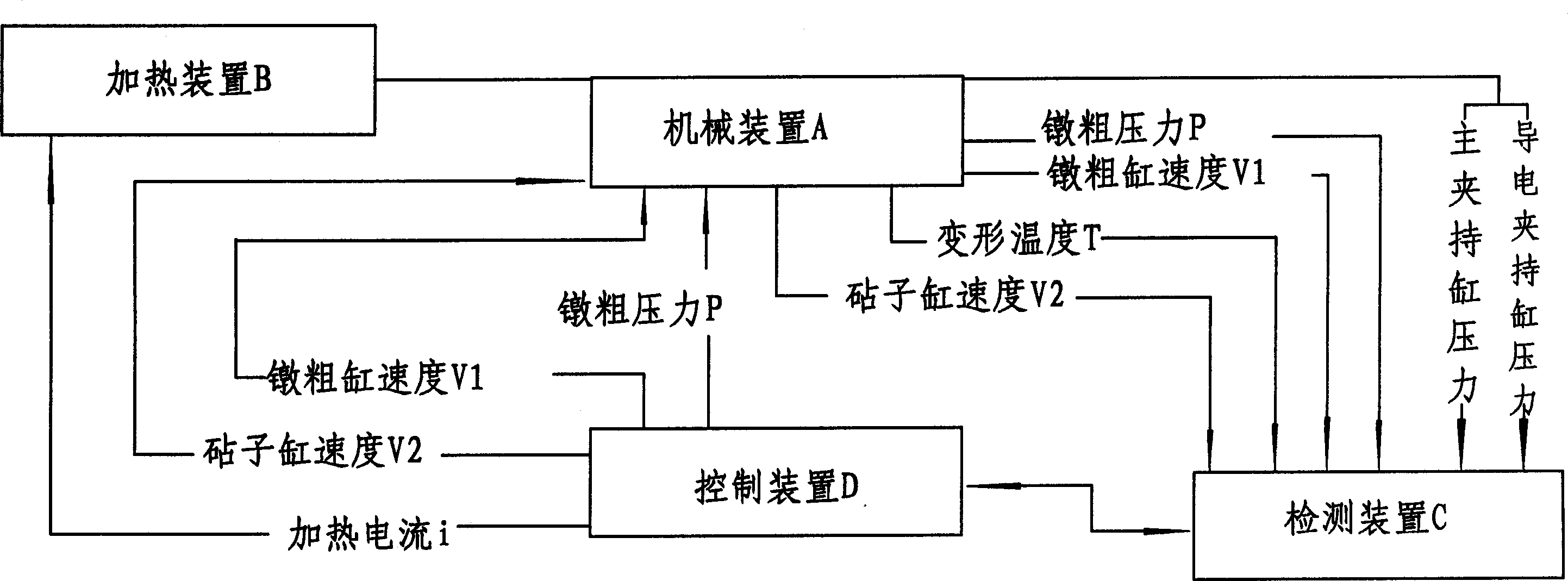
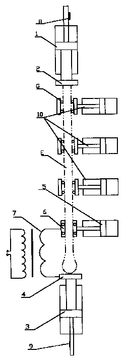
[0010] The structural principle diagram of the present invention is as figure 1 As shown, the control schematic diagram is shown as figure 2 As shown, include mechanical device A, heating device B, detection device C and its control device D, mechanical device A includes upsetting cylinder (1), upsetting block (2), anvil cylinder (3), anvil ( 4), the conductive clamping cylinder (5), the heating device B includes clamping electrodes (6), transformers (7), and the detection device C includes the upsetting cylinder (1) and the anvil cylinder (2). The displacement sensors (8, 9) on the piston, the upsetting block (2) and the anvil block (4) are fixed on the pistons of the upsetting cylinder (1) and the anvil cylinder (3) respectively, and the clamping electrode (6) is fixed Installed on the piston of the conductive clamping cylinder (5), the anvil (4) and the clamping electrode (6) are connected in series at both ends of the secondary coil of the transformer (7), and the workpi...


PUM


Abstract

The electric upsetter includes mechanical mechanism, heating mechanism, detection mechanism, and control mechanism. The mechanical mechanism includes upsetting cylinder, upsetting block, smithy cylinder, smithy block and conducting holding cylinder; the heating mechanism includes holding electrodes and transformer; the detection mechanism includes displacements mounted on the upsetting cylinder and the smithy cylinder separately; and the transformer is controlled with an electronic unit and continuously controlled output voltage. Based on the plastic mechanics and thermodynamic principles, the calculation method of heating current, upsetting pressure, speed and other technological parameters is given; and by means of the continuous closed loop control of speed, pressure, temperature and current, the optimal control of the electric upsetting process is realized.

Description

1. Technical field: [0001] The invention is an intelligent electric upsetting machine, in particular an electric upsetting machine for electrothermal upsetting of engine valves, which belongs to the innovative technology of mechatronics. 2. Background technology: [0002] At present, the intelligence level of electric upsetting machines is low, and the process parameters such as heating current, upsetting pressure, and speed can only be determined by experience in production. The main problems are as follows: (1) Each process parameter (pressure, speed, voltage, etc.) ) is a preset constant in a single working cycle, and parameter optimization cannot be realized; (2) After the working conditions (temperature, wear, blank quality, etc.) change during the working process, the system cannot automatically change to adapt to the changes in working conditions, To ensure the quality of the product; (3) Every time a product is replaced, the process parameters must be readjusted and ...

Claims


Application Information

Patent Timeline
Patent Type & Authority Applications(China)
IPC IPC(8): B21G3/12
Inventor 孙友松张弢郑泰胜罗天友张忠夫李区陈绮丽宁志坚陈健李振雄文元美李德章争荣罗有芬肖小亭梁锦生刘天湖
Owner GUANGDONG UNIV OF TECH
Learn More