
Air flow system for microwave oven

A technology of air flow and microwave ovens, which is applied in the field of microwave ovens, can solve the problems of increasing the manufacturing cost of microwave ovens, and achieve the effects of reducing manufacturing costs, improving performance, and reducing grilles

Inactive Publication Date: 2003-11-12
LG ELECTRONICS (TIANJIN) APPLIANCES CO LTD
View PDF0 Cites 5 Cited by
  • Summary
  • Abstract
  • Description
  • Claims
  • Application Information

AI Technical Summary

Problems solved by technology

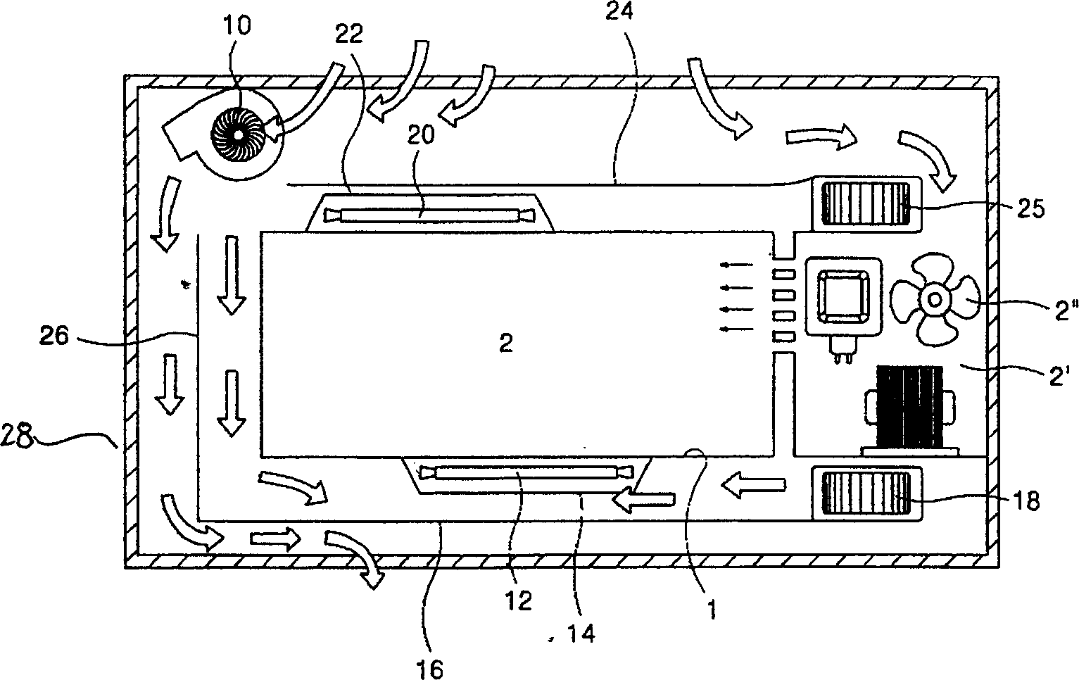
Moreover, due to the use of multiple fan assemblies 2", 10, 18, 25, the manufacturing cost of the microwave oven is increased

Method used


Image

  • Air flow system for microwave oven
  • Air flow system for microwave oven
  • Air flow system for microwave oven

Examples


Embodiment Construction

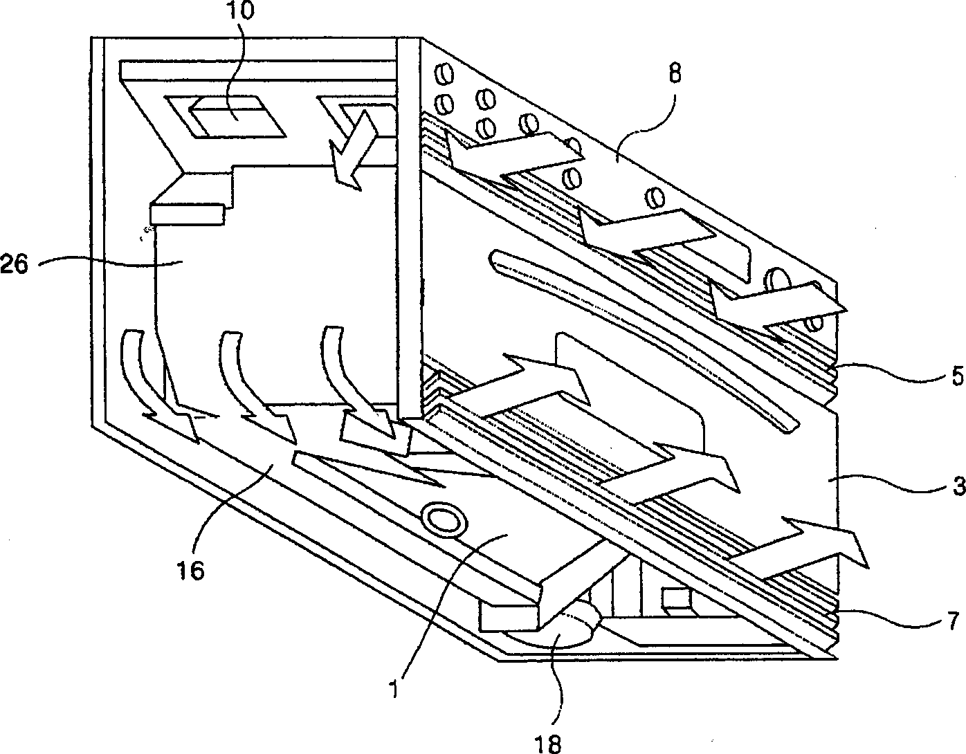
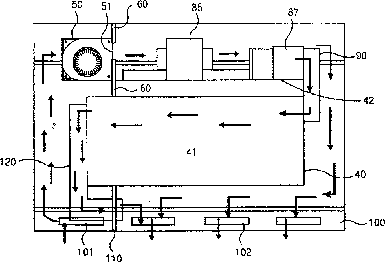
[0026] Below in conjunction with the accompanying drawings and specific embodiments, the air flow system of the microwave oven of the present invention is described in further detail:

[0027] like image 3 , 4 As shown, a conditioning chamber 41 for conditioning food is formed inside the microwave oven cavity 40 . An air flow generating device 50 is provided on the left side of the top surface 42 of the cavity, and the air flow generating device may be a suction fan assembly, the function of which is to inhale air from the outside to form an air flow inside the microwave oven. The air flow generating device 50 consists of a motor and agitating fans on both sides. The air sucked in from both ends is output through the output port 51 of the air flow generating device. A plate-shaped partition 60 including a first through hole 61 and a second through hole 62 is provided at a position corresponding to the airflow generator outlet 51 , and the partition 60 is provided adjacent ...


PUM


Abstract

The system comprises the inspiration part, the exhaustion part and the airflow generation part. The inspiration part sucks external air into the microwave oven. The exhaustion part including the grid in front of oven outputs the circulated air in oven to outside. The airflow generation part is located on one side of the cavity. With the parts outside the cavity being cooled by the airflow generated from the airflow generation part moved along the cavity, one part of the airflow through the exhaustion part is output forming the airflow to cool parts and the other part of the airflow is fed into the cavity. With being circulated, the airflow in the cavity through the exhaustion part is output. The invention reduces the part number of fan assembly, simplifies the installing technique, lowers the production cost and raises the noise level.

Description

technical field [0001] The present invention relates to microwave ovens, especially to a microwave oven air flow system with simplified internal structure. Background technique [0002] A microwave oven is a device that uses a voltage to generate microwaves and radiate the microwaves to the conditioner for heating. Generally speaking, the most basic heating method of microwave ovens is to irradiate microwaves to the conditioned object in the cavity, but this microwave heating method has relatively single characteristics, so recently people have installed auxiliary heaters inside microwave ovens as another heating method. source. Due to the auxiliary heating source, high temperature heat can be obtained in a short time, thereby improving the conditioning speed. However, a cooling device is additionally installed in order to avoid damage to each component at high temperature. Microwave ovens with this function can be roughly divided into general microwave ovens that are use...

Claims


Application Information

Patent Timeline
IPC IPC(8): F24C7/02F24C15/22
Inventor 李承建
Owner LG ELECTRONICS (TIANJIN) APPLIANCES CO LTD
Learn More