Method for writing double holographic grating at one time by single pulsed laser
A holographic grating, ultra-short pulse laser technology, applied in the field of holographic grating
- Summary
- Abstract
- Description
- Claims
- Application Information
AI Technical Summary
Problems solved by technology
Method used
Image
Examples
Embodiment 1
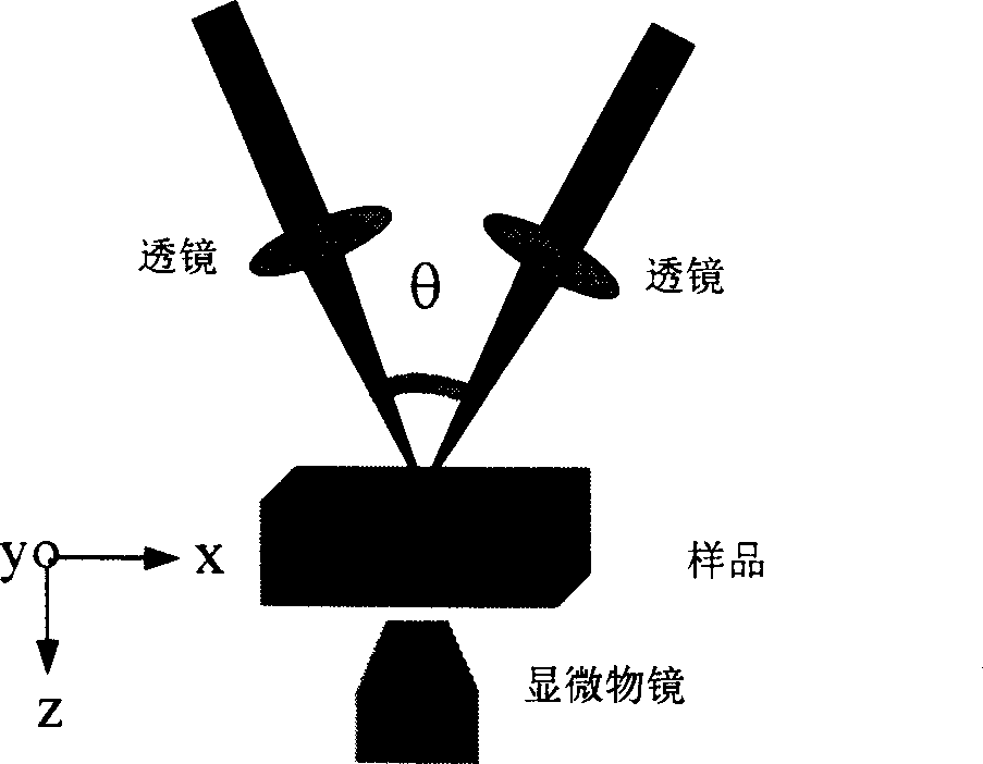
[0026] The selected pulse width is 50fs (5×10 -14 second) femtosecond pulse, the wavelength is 800nm, the pulse repetition rate is 1Hz, and the pulse energy is 70μJ. The beam is divided into two beams by the beam splitter, and the beam diameter is 6mm. The coherence of the two beams is achieved by frequency doubling crystal (BBO) generated second harmonic to achieve. The angle between the two beams of light is 45°, and the sample is controlled by a three-dimensional mobile platform operated by a computer. Use two focusing lenses with a focal length of 10cm to focus the two light beams at a distance of about 35 μm from the surface of the quartz glass, and the diameter of the spot at the focus is about 30 μm, so that a double holographic grating is formed on the surface of the quartz glass, and observed with an optical microscope (100 × objective lens) The result is as image 3 As shown, the structural period is 1 μm.
Embodiment 2
[0028] Similar to the way of embodiment 1, the selected pulse width is 120fs (1.2 × 10 -13 second) ultrashort pulse, the wavelength is 800nm, the pulse repetition rate is 5Hz, the pulse energy is 80μJ, the beam diameter is 6mm, and the angle between the two beams is 45°. The beams are focused and intersect at the focal point, and the intersection point is about 30 μm away from the surface of the lead glass. The spot diameters of the two beams at the focal point are 35 and 30 μm respectively, thus forming a double holographic grating on the surface of the lead glass, using an optical microscope (100 × objective lens) The observed results are as Figure 4 As shown, the structural period is 1 μm.
Embodiment 3
[0030] As in Example 1, the selected pulse width is 500fs (5 × 10 -13 second) ultrashort pulse, the wavelength is 800nm, the pulse repetition rate is 10Hz, the pulse energy is 90μJ, the angle between the two beams is 60°, and the two beams are focused by two focusing lenses with focal lengths of 20cm and 10cm The distance between the intersection point and the K9 glass surface is about 40 μm, and the spot diameters of the two beams at the focal point are 50 μm and 30 μm respectively, so that a double holographic grating is formed on the K9 glass surface, and the size of the two holographic gratings is obviously different. objective lens) observed results such as Figure 5 As shown, the structural period is 0.8 μm.
[0031] In summary, the present invention utilizes the ultrashort pulse laser with a single pulse width less than 1 ps to achieve coherent superposition in space and time after beam splitting, and can write double holographic micro-gratings in a solid transparent m...
PUM
 Abstract
Description
Claims
Application Information
 - R&D
- Intellectual Property
- Life Sciences
- Materials
- Tech Scout
- Unparalleled Data Quality
- Higher Quality Content
- 60% Fewer Hallucinations
Browse by: Latest US Patents, China's latest patents, Technical Efficacy Thesaurus, Application Domain, Technology Topic, Popular Technical Reports.
© 2025 PatSnap. All rights reserved.Legal|Privacy policy|Modern Slavery Act Transparency Statement|Sitemap|About US| Contact US: help@patsnap.com


