Flow control valve and sphygmomanometer

A technology for flow control valves and inflow ports, which is applied to valve details, valve devices, blood vessel evaluation, etc., can solve problems such as insufficient crimping force, increased power consumption, and enlarged size, and achieves small size, low power consumption, and poor operation Effects with few, simple structures

Inactive Publication Date: 2003-08-06
OMRON HEALTHCARE CO LTD
View PDF3 Cites 13 Cited by
  • Summary
  • Abstract
  • Description
  • Claims
  • Application Information

AI Technical Summary

Problems solved by technology

However, in the structure shown in FIGS. 15A and 15B , there are: the thrust formed by the electromagnetic force generated by the electromagnetic coil 6 cannot be effectively utilized, and the flow rate control that requires a large valve load (hole seal 3 to the inflow port 1a) of the crimping force Problems with increased size and increased power consumption in valves
[0011] That is, in the flow control valve shown in FIGS. 15A and 15B, since the pressure contact force of the orifice seal member 3 to the inflow port 1a is not so large, in the wrist sphygmomanometer, a greater pressure is required than that of the finger sphygmomanometer. The crimping force is insufficient, and the inflow port 1a may not be completely closed when the envelope is pressurized above the maximum pressure value.
In order to avoid this, a larger crimping force will be created, which will cause the problem of increasing the flow control valve and increasing power consumption.
[0012] In addition, in the flow control valve shown in Figs. 15A and 15B, when receiving an impact such as falling, the permanent magnet 5 is often cracked due to its brittleness, resulting in a problem of poor flow control characteristics.

Method used


Image

  • Flow control valve and sphygmomanometer
  • Flow control valve and sphygmomanometer
  • Flow control valve and sphygmomanometer

Examples


Embodiment Construction

[0048] The present invention is illustrated below by means of examples.

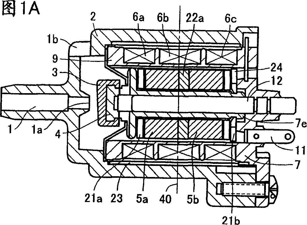
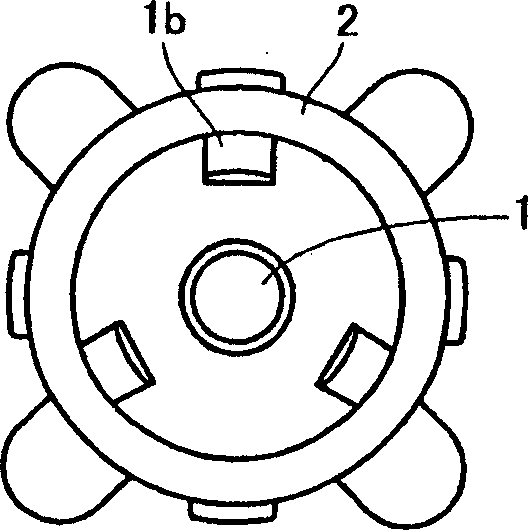
[0049] The flow control valve of one embodiment thereof is shown in Fig. 1A (schematic sectional view) and Figure 1B (left side view). On the other hand, the same symbols are assigned to the same elements as those shown in FIGS. 15A and 15B .

[0050] The flow control valve of this embodiment has used two permanent magnets 5a, 5b and three electromagnetic coils 6a, 6b, 6c; The housing is formed by the rear part of the frame housing 2 and the coil skeleton 7 equivalent to the aforementioned front cover, This housing (frame housing 2 ) has a gas inlet 1a in which a nozzle-shaped inner pipe 1 opens, and a plurality (here, three) of gas outlets 1b communicating with the gas inlet 1a through an internal space.

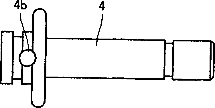
[0051] Inside this housing, Figure 2A , 2B The shown hollow actuating shaft (movable member) 4 can be arranged forwardly and backwardly with respect to the inflow port 1a. In order to open and c...


PUM


Abstract

A flow control valve, comprising a frame case (2) having a gas inlet (1a) and a gas outlet (1b), an operating shaft (4) disposed so as to be allowed to move close to and away from the inlet (1a), and an orifice packing (3) installed at the tip of the operating shaft and opening and closing the inlet (1a), wherein two permanent magnets (5a, 5b) are installed on the operating shaft (4) through a yoke (22a) in the state where the same electrodes thereof are opposed to each other and three electromagnetic coils (6a, 6b, 6c) are disposed on the outside of the permanent magnets (5a, 5b) in the state where the winding directions of the coils positioned adjacent to each other are reverse to each other and, when a current flows through the electromagnetic coils (6a, 6b, 6c), electromagnetic forces generated by the electromagnetic coils (6a, 6b, 6c) and the permanent magnets (5a, 5b) are combined with each other, the operating shaft (4) is moved leftward by the combination thrust as shown in the figure so that the orifice packing (3) closes the inlet (1a), whereby the flow control valve of small size with less power consumption and less mal-function can be provided by effectively utilizing the thrust by the electromagnetic force while the structure thereof is simple.

Description

technical field [0001] The present invention relates to a flow control valve used, for example, as an air discharge device in a sphygmomanometer, and a sphygmomanometer having such a flow control valve. Background technique [0002] Various proposals have been made for sphygmomanometers. Among them, there is a sphygmomanometer that measures a person's blood pressure during the depressurization process after the pressure in the envelope is raised to a predetermined value, and then the pressure is gradually lowered. In such a sphygmomanometer, there is a "flow control valve" disclosed in Japanese Patent Application Laid-Open No. 6-47008 as a flow control valve for gradually reducing the pressure in the cuff. The flow control valve described in this publication forms a pressure inflow port (gas inflow port) and a pressure outflow port (gas outflow port) in the front housing, supports the drive shaft in a forward and backward manner relative to the gas inflow port, and Install ...

Claims


Application Information

Patent Timeline
Patent Type & Authority Applications(China)
IPC IPC(8): A61B5/022A61B5/0235F16K31/06F16K31/08
CPCA61B5/0235F16K31/082F16K31/0679
Inventor 福井了一松田寿臣
Owner OMRON HEALTHCARE CO LTD
Why Eureka
Try Eureka