
Cache line flush micro-architectural implementation method ans system

A buffer memory and high-speed cache technology, which is applied in the direction of memory system, instrument, memory address/allocation/relocation, etc.

Inactive Publication Date: 2003-06-18
INTEL CORP
View PDF0 Cites 8 Cited by
  • Summary
  • Abstract
  • Description
  • Claims
  • Application Information

AI Technical Summary

Problems solved by technology

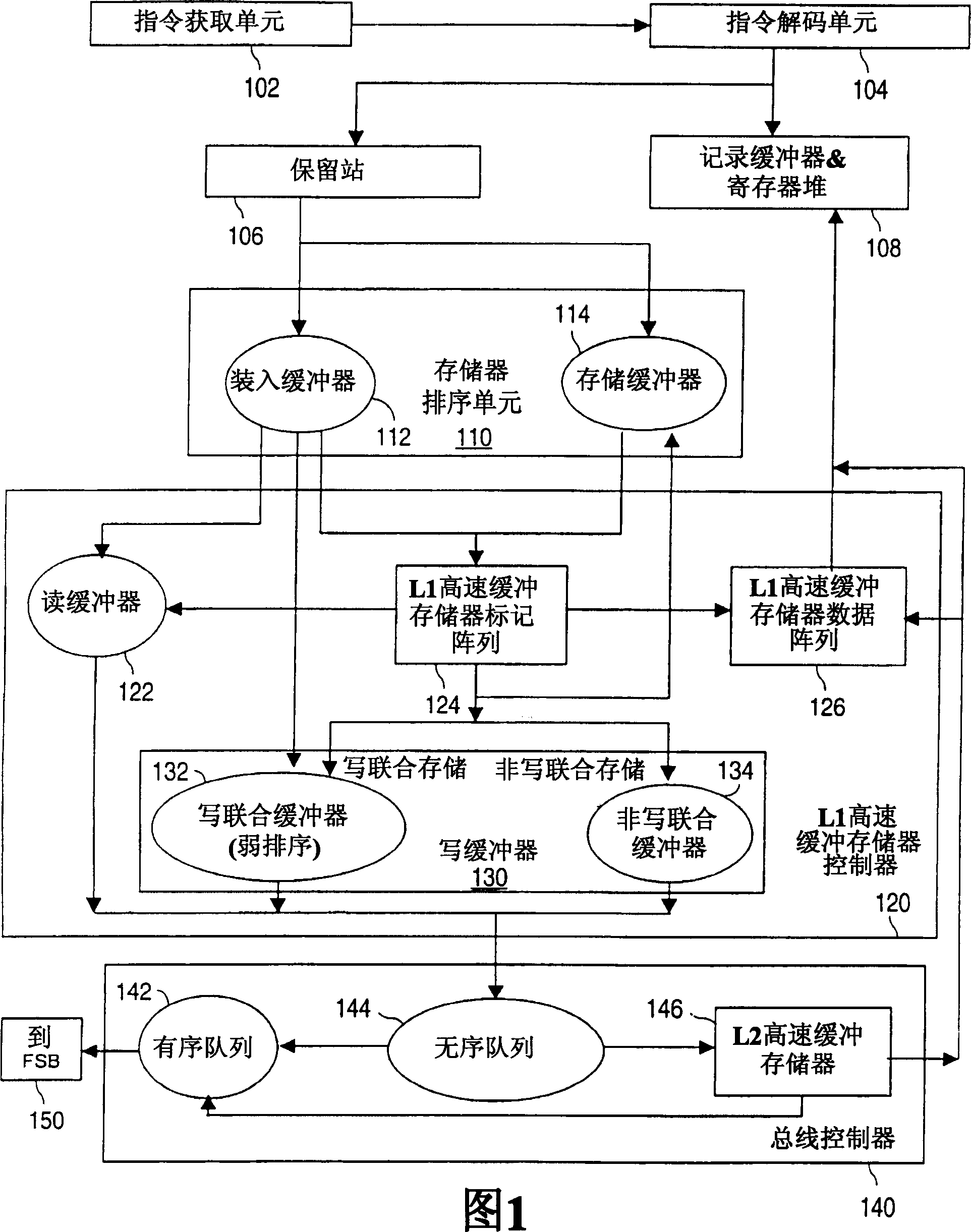
The problem with current systems is that high bandwidth between the cache memory and system memory is required to accommodate the copying of the write-join memory and the write-back memory

Method used


Image

  • Cache line flush micro-architectural implementation method ans system
  • Cache line flush micro-architectural implementation method ans system
  • Cache line flush micro-architectural implementation method ans system

Examples


Embodiment Construction

[0016] By definition, a cache line is either completely valid or completely invalid. A cache line is never partially valid. For example, when the processor only wants to read one byte, all bytes for an applicable cache line must be stored in cache; otherwise, cache "misses" may occur. The cache lines form the actual cache memory. The cache directory is used only for cache management. A cache line typically contains more data than it can potentially translate in a single bus cycle. To this end, most cache memory controllers implement burst mode, in which a pre-set sequence of addresses enables data to be transferred across the bus more quickly. This is used for cache line fills, or for writing back cache lines, since these cache lines represent a contiguous and aligned region of addresses.

[0017] Techniques for flushing cache lines may be associated with linear memory addresses. When executed, this technique flushes cache lines associated with operands from all caches in...


PUM


Abstract

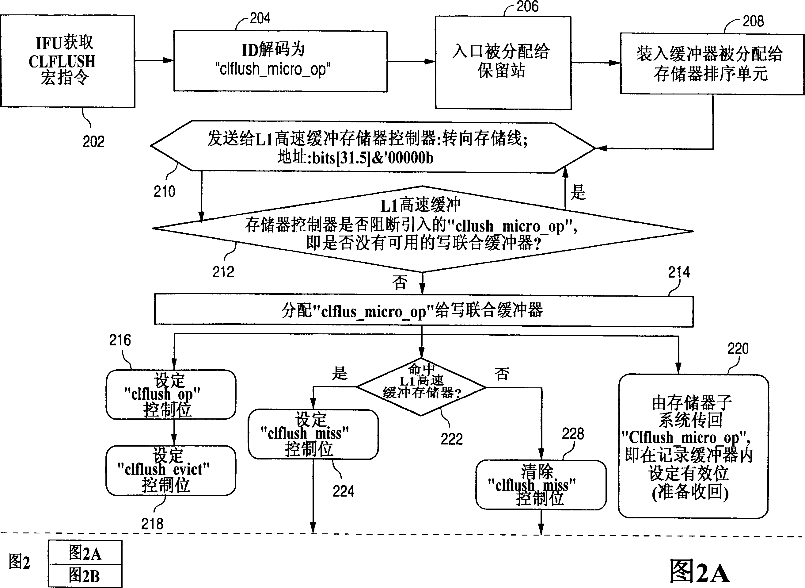
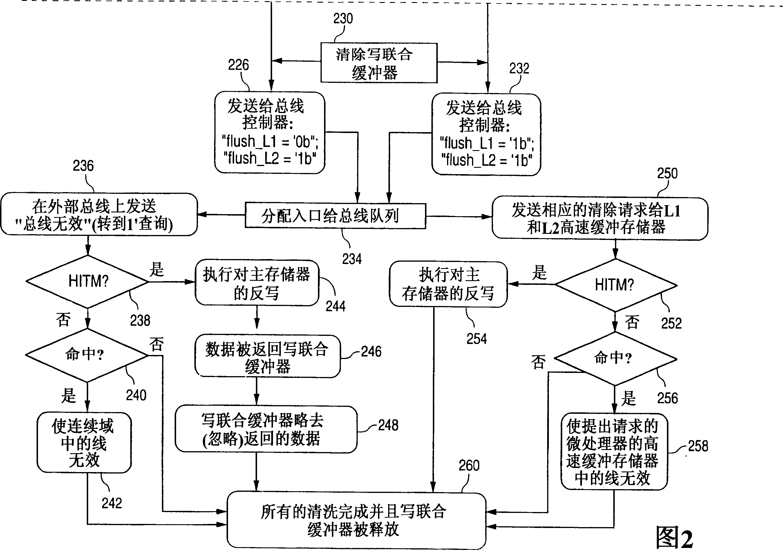
A system and method for flushing a cache line associated with a linear memory address from all caches in the coherency domain. A cache controller receives a memory address, and determines whether the memory address is stored within the closest cache memory in the coherency domain. If a cache line stores the memory address, it is flushed from the cache. The flush instruction is allocated to a write-combining buffer within the cache controller. The write-combining buffer transmits the information to the bus controller. The bus controller locates instances of the memory address stored within external and intel cache memories within the coherency domain; these instances are flushed. The flush instruction can then be evicted from the write-combining buffer. Control bits may be used to indicate whether a write-combining buffer is allocated to the flush instruction, whether the memory address is stored within the closest cache memory, and whether the flush instruction should be evicted from the write-combining buffer.

Description

technical field [0001] The present invention relates generally to computer architecture, and in particular to a system and method that allows a processor to flush cache lines associated with linear memory addresses from all caches in a contiguous domain. Background technique [0002] A cache memory device is a small, fast memory that can be used to store the most frequently accessed data (or "words") from a larger, slower memory. [0003] Dynamic Random Access Memory (DRAM) provides high-capacity storage at low cost. Unfortunately, DRAM access is too slow relative to modern microprocessors. A cache that offers a cost-effective solution provides a static random access memory (SRAM) cache, or a cache that is physically installed on the processor. Even though the cache memory has a relatively small storage capacity, it still enables high-speed access to the data stored therein. [0004] The principle of operation of the cache memory is described below. When an instruction o...

Claims


Application Information

Patent Timeline
IPC IPC(8): G06F12/08
CPCG06F12/0804G06F12/0811
Inventor 萨尔瓦多·帕朗卡斯蒂芬A·菲希尔苏布拉马尼亚姆·迈尤兰
Owner INTEL CORP
Learn More