Energy-saving long-life electric fan and its manufacture method

An electric fan and long-life technology, which is applied in the direction of non-variable pumps, pump devices, machines/engines, etc., can solve the problems of low working efficiency and long service life of fans, and achieve increased strength, rigidity and working efficiency High, the effect of output power improvement

Inactive Publication Date: 2003-06-11
应恩甫 +1
View PDF0 Cites 0 Cited by
  • Summary
  • Abstract
  • Description
  • Claims
  • Application Information

AI Technical Summary

Problems solved by technology

That is to say, the working efficiency of this kind of fan is not too high, and the service life is not too long
And this type of motor can only be suitable for small-power and small-diameter breeze fans

Method used


Image

  • Energy-saving long-life electric fan and its manufacture method
  • Energy-saving long-life electric fan and its manufacture method
  • Energy-saving long-life electric fan and its manufacture method

Examples


Embodiment Construction

[0010] specific implementation plan

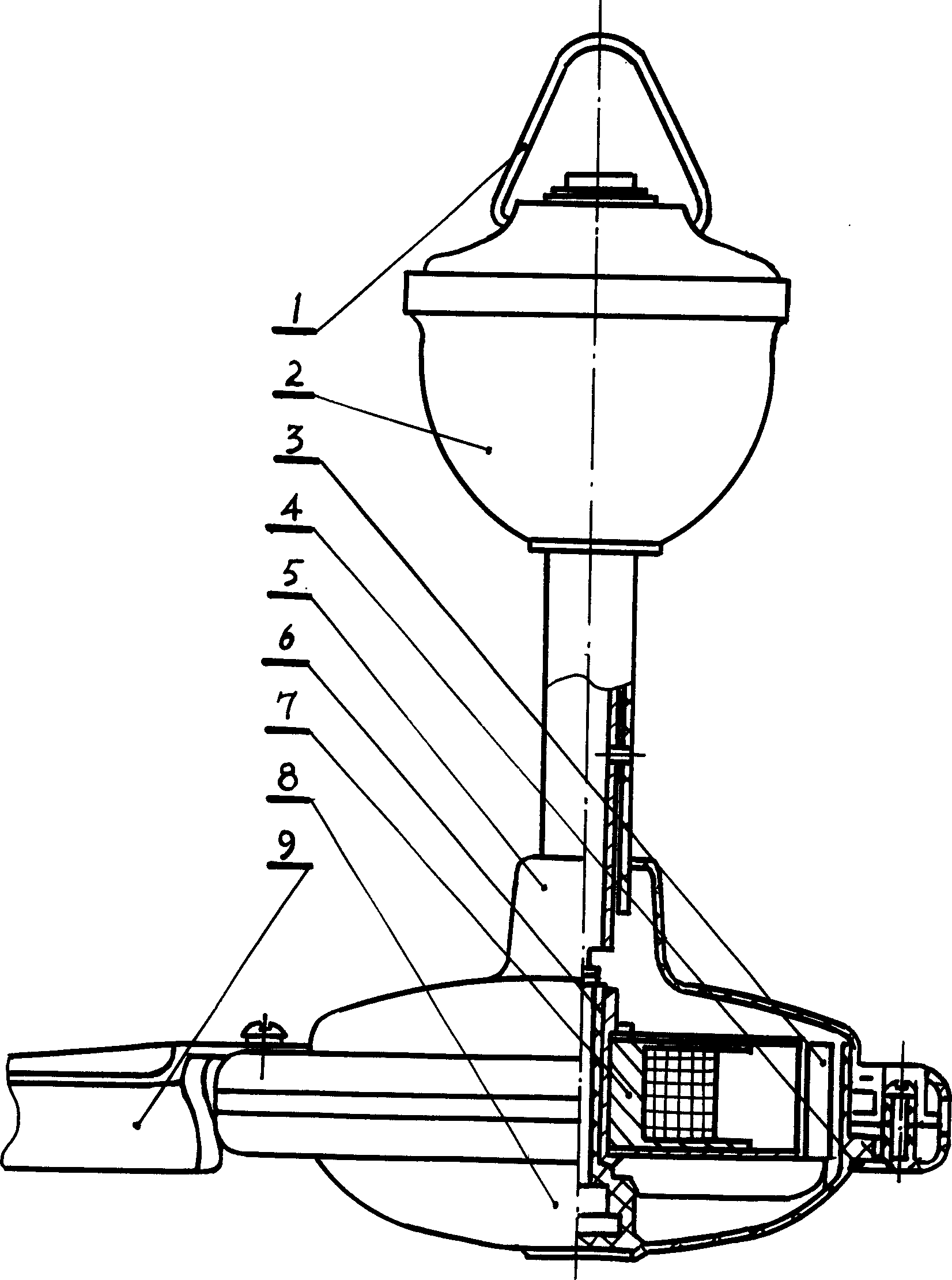
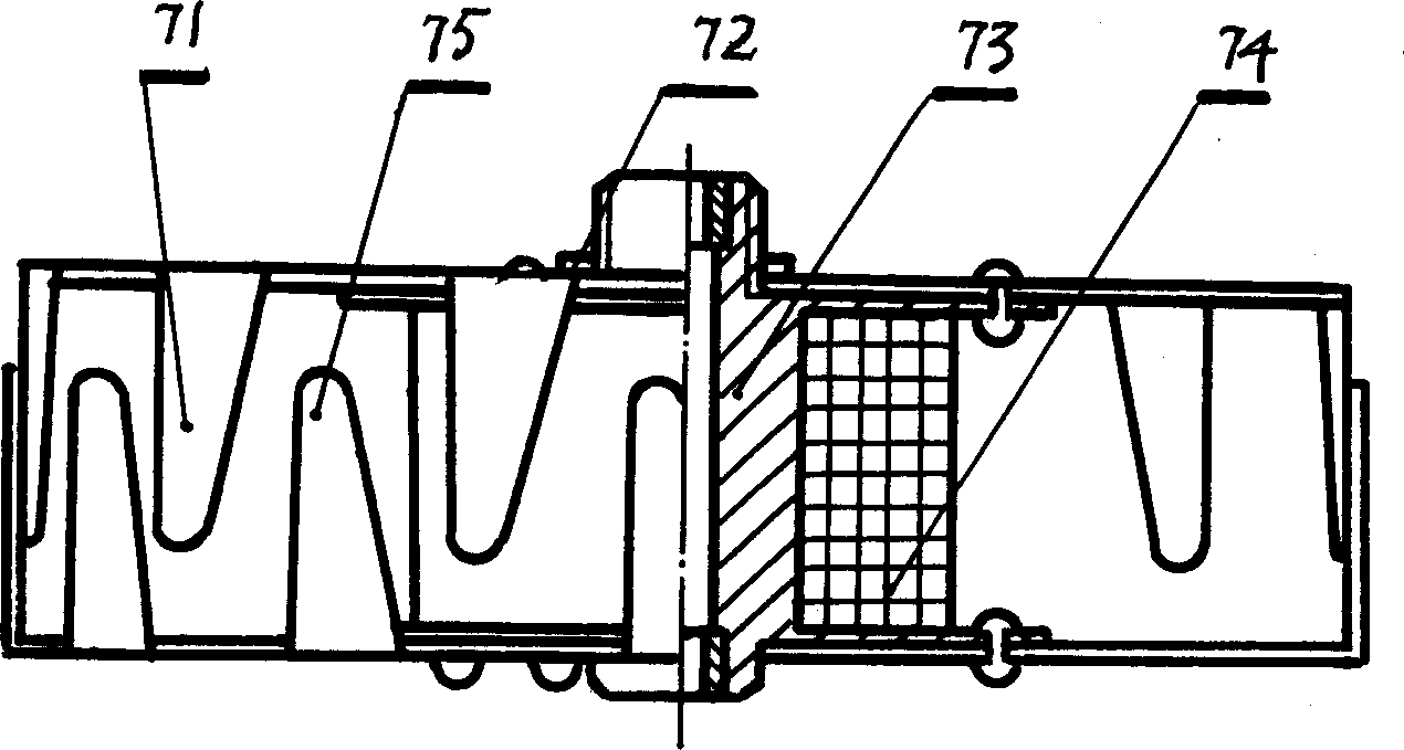
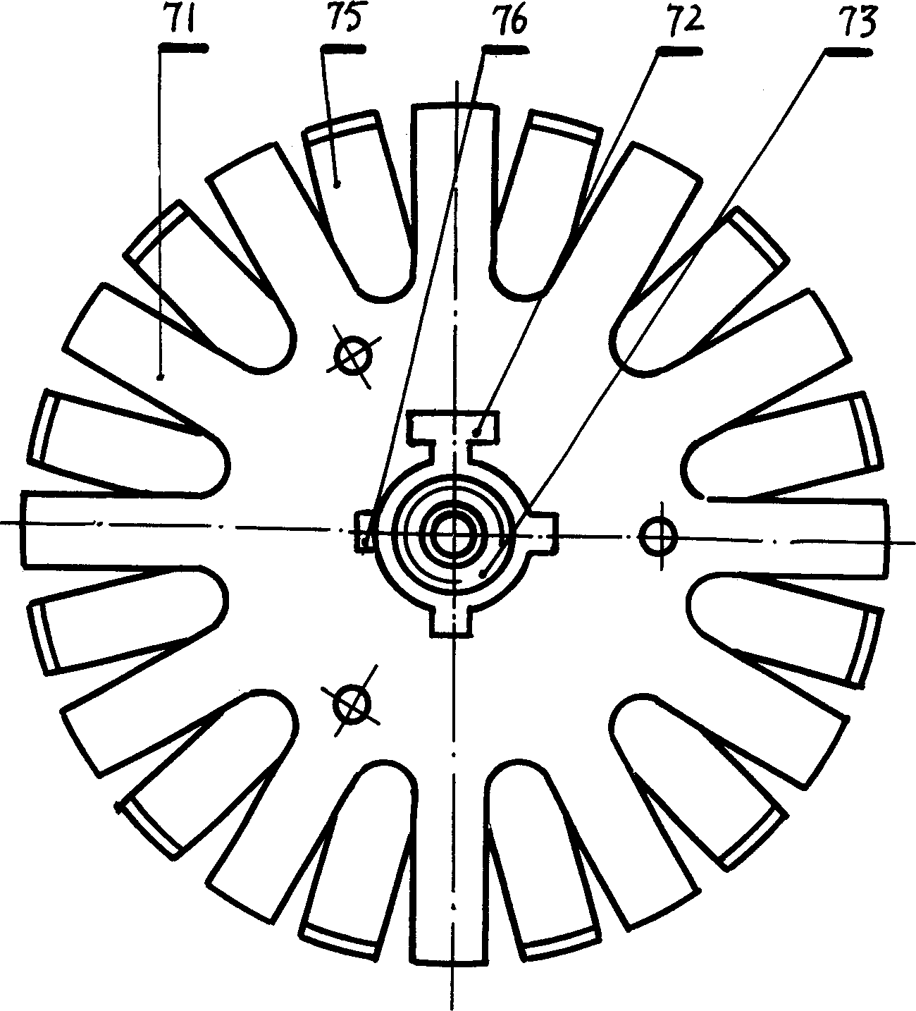
[0011] as attached Figure 1-10 As shown, the energy-saving and long-life electric fan includes a lower end cover 8 and an upper end cover 5 fixed thereon, an armature assembly 7 installed in the upper end cover 5 and the lower end cover 8 and fixed on the main shaft 6, and an armature assembly 7 fixed on the lower end cover 8 Magnetic sheet 3, starter box assembly 2 and suspension ring 1 fixed on the main shaft 6, fan blade 9 fixed on the outer rotor. The armature assembly 7 includes a wire frame core 73 , a coil 74 wound on the wire frame core 73 , and an upper claw pole 71 and a lower claw pole 75 fixed on the wire frame core 73 . The wire frame iron core 73 is composed of an iron core 733 , an upper end plate 731 fixed on the iron core 733 and a lower end plate 732 to form a part. There is an integrated bearing screw on the iron core 733 . The upper and lower ends of the iron core 733 are equipped with oil-im...


PUM


Abstract

The invention is longevous fan and the manufacturing method. It refers to single-phase alternating claw pole magneto synchronous electrical machine, especially refers to the fan with electrical machinery made up by in field armature and magneto out rotator. It includes up and down end cap, armatures, magnetism slices, starting box and flying rings. The armature comprises iron core, coils, up and down claw pole. The wire frame ion core is made up of iron core, part made up of up and down end boards, cross section of iron core and coils aren't rounded, the wire frame iron core, up and down end board are made up from magnetism materials. The up and down end boards are welded or rivet jointed on iron core, the up and down claws are fixed on up and down end boards.

Description

technical field [0001] The invention relates to a single-phase AC claw-pole permanent magnet synchronous motor fan, in particular to an electric fan composed of an inner excitation armature and a permanent magnet outer rotor motor. Background technique [0002] Existing electric fan with internal excitation armature and permanent magnet outer rotor motor, its internal excitation armature is made up of coil, upper and lower claw poles, iron core, bearing screw, pressure plate and main shaft. Each part is fastened on the main shaft by bearing screws. Because there are many parts, the diameter of the armature is large, the torque is large, and the bearing screw cannot be too large, so the fastening force cannot be large. When the fan is running, there will be looseness between the parts, which will shorten the life of the fan. Secondly, the coil frame is made of non-metallic material, the winding place is thin-walled, and the coil is round after win...

Claims


Application Information

Patent Timeline
IPC IPC(8): F04D25/08
Inventor 应恩甫应利沙
Owner 应恩甫
Why Eureka
Try Eureka