Stator slot holder with closed-loop stabilizer

A technology of stabilizing device and stator wire, applied in the direction of magnetic circuit shape/style/structure, magnetic circuit static parts, etc., can solve the problems of reducing the winding space of the wire slot, reducing the occupancy rate of the stator coil wire slot, etc., to eliminate the Friction noise, elimination of wobble, effect of wobble elimination

Inactive Publication Date: 2003-01-29
许俊甫
View PDF0 Cites 1 Cited by
  • Summary
  • Abstract
  • Description
  • Claims
  • Application Information

AI Technical Summary

Problems solved by technology

[0003] To manufacture a motor with high operating efficiency, most of the manufacturing bottlenecks occur in the coil winding of the stator teeth, because there must be relatively high magnetic loading and electrical loading in order to have high operating efficiency, and the electrical loading involves the stator part. The number of coils and the thickness of the wire diameter of the coil, a higher electrical load means a higher current density, and a higher current density must also have a stator coil with a thicker wire diameter for higher current flow Among them, since the traditional inner rotor motor stator 51 and the outer rotor motor stator 61 are integrally formed (as shown in Figure 1), in order to increase the occupation rate of the traditional stator slots, the neat winding method of arranging the wires in a row is adopted (As shown in Figure 1 winding portion 513,613), the notch 511,611 of its stator tooth portion 512,612 enters and exits the path travel of winding coil (as shown in Figure 1 winding guide pin travel space 514, 614) thus reducing the slot winding space, that is, reducing the occupation rate of the stator coil slot, so at a certain torque constant K T value or back EMF constant K E The number of turns of the stator coil is constant under the condition of the value of the stator coil. Therefore, at a lower slot occupation ratio, the wire diameter of the stator coil must become thinner and smaller. Once the wire diameter becomes smaller and thinner, the high wire impedance will make The coil generates high temperature due to current flow (P=I 2 R), the high-temperature coil will cause the coil impedance to increase due to the physical properties of the metal. After this vicious cycle, the energy will be mostly consumed in the wire diameter impedance of the stator coil and converted into completely useless heat energy.

Method used


Image

  • Stator slot holder with closed-loop stabilizer
  • Stator slot holder with closed-loop stabilizer
  • Stator slot holder with closed-loop stabilizer

Examples


Embodiment Construction

[0040] specific implementation plan

[0041] Embodiments of the present invention will be illustrated by the following description.

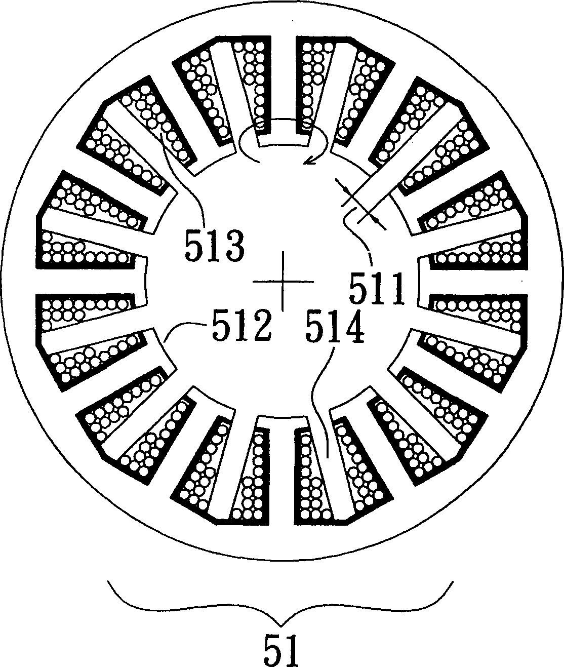
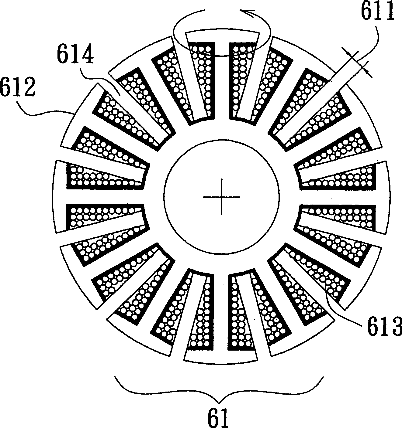
[0042] Please refer to Fig. 2 to Fig. 7, the stator slot seat 20 of the present invention has a ring-closed stabilizing device structure, including:

[0043] Most of the stator tooth magnetizers 31 with arc-shaped surfaces are separated from the mosaic grooves 211 and 212 of the annular magnetizer 21 of the stator.

[0044]A plurality of tooth slot seats 41, 418, 419, 420, which have: the back end 424 of the back side of the arc-shaped tooth surface 313 of the stator tooth magnetizer 31 can be engaged with; The left and right ends of the back end 424 form both side elevations 414, 415, 417, and the adjacent side elevations are formed correspondingly to each other and can be joined to each other's left and right elevations 414, 415, 417; The longitudinal vertical column 425 of the upper trunking seat 41, 420 provides the stator coil part 411 of...


PUM


Abstract

In order to improve the running efficiency of motors and dynamotor, the stator tooth section is separated from the stator section into individual bodies, then which are filled in the insulated neck groove seat with the loop-closed stabilizing device. Thus, the stator coil possesses higher fill in ratio. Two profile planes are built on the left and right end of the back face of the groove seat. The two profile planes constitutes the loop-closed stabilizing juncture so as to eliminate the excitation oscillation generated by the reaction between the recombined stator body and the armature of therotator magnet. Moreover, the intensity of the mechanical structure of the recombined stator section is strengthened so as to keep the operation in stable state.

Description

technical field [0001] The invention relates to a stator wire slot seat with a ring closure stabilizing device structure, in particular to a kind of two side elevations established at the left and right ends of adjacent stator wire slot seats, and correspondingly matched with each other for ring closure and stable joint. Background technique [0002] In the industry that consumes a lot of energy, the requirements for the operating efficiency of motors and generators have become an important course in current manufacturing technology. Neither the operating efficiency nor the economic efficiency of the manufacturing process can be ignored. [0003] To manufacture a motor with high operating efficiency, most of the manufacturing bottlenecks occur in the coil winding of the stator teeth, because there must be relatively high magnetic loading and electrical loading in order to have high operating efficiency, and the electrical loading involves the stator part. The number of coils...

Claims


Application Information

Patent Timeline
IPC IPC(8): H02K1/16
Inventor 许俊甫
Owner 许俊甫
Why Eureka
Try Eureka