
Phase-locked loop frequency synthesizer with digital coarse tuning loop

A frequency synthesizer and coarse tuning technology, applied in the direction of automatic power control, electrical components, etc., can solve the problems of increasing the cost of frequency synthesis, low integration, and no degradation of frequency synthesis performance, and achieves a reduction in frequency locking time, Improves tuning speed and reduces phase noise

Inactive Publication Date: 2003-01-01
TSINGHUA UNIV
View PDF0 Cites 13 Cited by
  • Summary
  • Abstract
  • Description
  • Claims
  • Application Information

AI Technical Summary

Problems solved by technology

[0005] 1) The voltage control signal output by the phase detector changes slowly with the change of VCO frequency, so the frequency tuning process of the entire voltage controlled oscillator is very long, making it unable to be used for frequency hopping communication that requires a high frequency locking time system
[0006] 2) Secondly, because the standard CMOS process cannot integrate high-precision, high-performance inductors and capacitors on the chip, and at the same time it is necessary to ensure that the frequency synthesis performance does not decline, the usual integration method is to place the VCO outside the entire frequency synthesis chip. As a result, the integration level is not high, and the cost also increases
[0007] 3) In addition, since the filter capacitance that constitutes the loop filter is too large, it is difficult to integrate the chip. Therefore, the loop filter can only be placed outside the chip as a discrete component, thereby increasing the frequency synthesis cost
[0008] In the process of wireless transceivers becoming more and more single-chip design, the above factors restrict the high integration of traditional PLL frequency synthesizers, and it is impossible to realize single-chip design to save costs. Therefore, a frequency synthesizer with a new structure is developed to adapt to single-chip Integration becomes a pressing issue

Method used

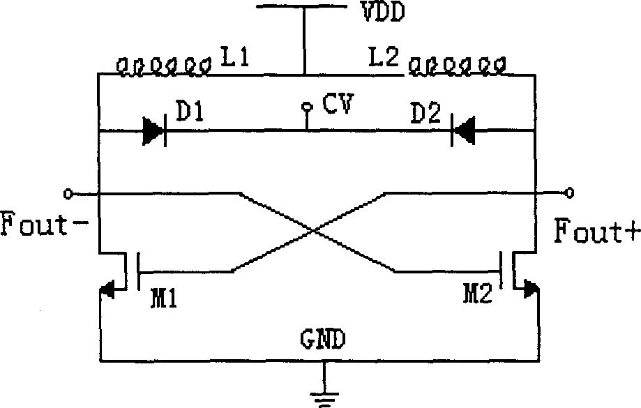

Image

  • Phase-locked loop frequency synthesizer with digital coarse tuning loop
  • Phase-locked loop frequency synthesizer with digital coarse tuning loop
  • Phase-locked loop frequency synthesizer with digital coarse tuning loop

Examples


Embodiment Construction

[0021] The structure and operating principle of a kind of PLL frequency synthesizer with high precision digital coarse tuning loop that the present invention proposes are described in detail as follows in conjunction with accompanying drawing and embodiment:

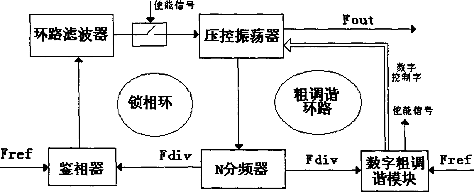
[0022] The overall structure of frequency synthesis of the present invention is as image 3 As shown, it includes two tuning loops, in which the phase-locked loop is still composed of a phase detector, a loop filter, a voltage-controlled oscillator and an N frequency divider. The connection relationship and working principle are the same as those of the traditional PLL frequency Comprehensively the same; the increased coarse tuning loop consists of a voltage-controlled oscillator, an N frequency divider, and a digital coarse tuning module connected to the output of the voltage-controlled oscillator and the input of the N frequency divider. In this frequency synthesis structure, the voltage-controlled oscillator and the N...


PUM


Abstract

The present invention belongs to the field of frequency synthesizer design in radio transceiver and relates to phase-locked loop frequency synthesizer with digital coarse tuning loop. The frequency synthesizer includes a phase-locked loop comprising phase discriminator, loop filter, voltage-controlled vibrator and N frequency divider and a coarse tuning loop comprising the voltage-controlled vibrator, the N frequency divider and digital coarse tuning module. The present invention uses one groups of fixed capacitors to constitute partial variable capacitor and controls the amount of the resonant capacitance digital to tune the VCO output frequency. The present invention can compensate the manufacture error of integrated inductors and variable capacitor tube in chip, reduce the frequency synthesizing locking time, reduce VCO phase noise, reduce the capacitance in loop filter.

Description

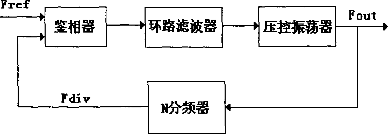
technical field [0001] The invention belongs to the technical field of wireless transceivers, in particular to an improved design of a frequency synthesizer structure. Background technique [0002] Frequency synthesizer (referred to as frequency synthesizer) is a key module in the design of wireless transceivers. It obtains the same stability by performing four arithmetic operations of addition, subtraction, multiplication, and division on a high-stability, high-precision reference frequency. , A series of frequencies with high precision, so as to provide the local oscillator signal for the channel selection in the transceiver, and input it to the local oscillator terminal of the mixer. Common frequency synthesis structures include phase-locked (PLL) frequency synthesizer, direct digital frequency synthesizer and fractional-N frequency synthesizer, but the most used one is PLL frequency synthesis. The structure is as follows figure 1 As shown, a phase-locked loop is compose...

Claims


Application Information

Patent Timeline
Patent Type & Authority Applications(China)
IPC IPC(8): H03L7/187
Inventor 李永明赵国光
Owner TSINGHUA UNIV
Learn More